Modular Design and Hot Swap Maintenance of Standard Rack Mount High Voltage Power Supply
Standard rack mount high voltage power supplies provide the mechanical and electrical interface for integration into instrument racks and control systems. The modular design approach enables configuration flexibility, simplified maintenance, and scalability for different voltage and current requirements. Hot swap capability allows modules to be replaced without powering down the system, maximizing uptime for critical applications. The design must address the electrical, mechanical, and safety considerations for reliable hot swap operation.
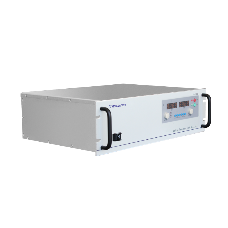
Rack mount power supplies conform to standard dimensions for mounting in equipment racks, typically based on the unit of height. The front panel provides controls, displays, and indicators for local operation and monitoring. The rear panel provides electrical connections for input power, output voltage, control signals, and status outputs. The mechanical design ensures structural integrity, proper ventilation, and compatibility with rack mounting hardware.
Modular design divides the power supply functionality into modules that can be independently specified, manufactured, and replaced. Common module types include the controller module that manages the overall operation, the power module that generates the high voltage, the interface module that provides communication and control, and the filter module that conditions the output. Each module has a defined electrical interface and mechanical form factor.
The benefits of modular design include configuration flexibility, where different module combinations provide different voltage and current ratings. Maintenance benefits include the ability to replace failed modules without replacing the entire unit. Scalability benefits include the ability to add modules for higher power or additional outputs. Manufacturing benefits include standardized module production and reduced inventory complexity.
Hot swap capability allows modules to be inserted and removed while the system remains powered and operational. This capability requires electrical and mechanical design features that prevent damage during insertion and removal, and that maintain system operation during the transition. Hot swap is valuable for systems requiring high availability, where downtime for maintenance is unacceptable.
Electrical design for hot swap includes precharge circuits that limit the inrush current when a module is inserted. The module input capacitance would otherwise draw a large current spike when first connected, potentially damaging connectors or disturbing the system power. Precharge circuits use resistors or active circuits to limit the initial current, then bypass the limiting element once the capacitance is charged.
Connector design for hot swap uses staged contacts that make and break connections in a defined sequence. The ground connection makes first and breaks last, ensuring that the module is grounded before any power or signal connections are made. The power connections make after ground, and the signal connections make last. This sequencing prevents floating modules and ensures safe insertion and removal.
Isolation and bypass circuits maintain system operation when a module is removed. In redundant configurations, the remaining modules carry the load without interruption. In nonredundant configurations, the output may be lost during module replacement, but the system remains ready to resume operation when the new module is inserted. The isolation circuits prevent the removed module from affecting the system.
Software and firmware support for hot swap includes module identification, configuration management, and status reporting. The system identifies the module type and capabilities when a new module is inserted, enabling automatic configuration. The system tracks the module status and history for maintenance planning. The user interface indicates the module status and guides the maintenance procedure.
Safety considerations for hot swap include protection against electrical shock, prevention of module damage, and assurance of system integrity. Interlocks may prevent module removal when the output is enabled or when dangerous conditions exist. The module design ensures that no hazardous voltage is accessible during handling. The system verifies that the replacement module is appropriate before enabling operation.
Thermal management in modular systems ensures that each module operates within its temperature rating and that the overall system cooling is adequate. Module power dissipation varies with the operating conditions, and the cooling system must handle the maximum expected dissipation. Temperature monitoring detects cooling problems before they cause failures. The modular design allows cooling components to be replaced independently if needed.
Testing and validation of hot swap capability verify that the system operates correctly through insertion and removal cycles. Testing includes electrical testing of the precharge and isolation circuits, mechanical testing of the connector sequencing, and system testing of the operation during and after module replacement. The testing validates the design under the expected operating conditions and usage patterns.