Multi-pulse Laser High Voltage Power Supply Synchronization System for Volume 3D Particle Tracking Velocimetry
Volume three-dimensional particle tracking velocimetry has emerged as a powerful technique for measuring complex flow fields in fluid dynamics research and industrial applications. The technique employs multiple laser pulses to illuminate tracer particles suspended in the flow, capturing images from multiple viewing angles to reconstruct three-dimensional particle positions and velocities. The high voltage power supplies that drive the laser systems must be precisely synchronized to generate pulses with appropriate timing relationships for accurate velocity measurement.
The fundamental principle of volume three-dimensional particle tracking velocimetry involves illuminating tracer particles at multiple time instances and capturing images from multiple camera positions. The particle positions at each time instance are reconstructed from the multiple camera views through triangulation algorithms. The particle displacements between time instances enable calculation of three-dimensional velocity vectors. The accuracy of velocity measurements depends critically on the timing precision of the laser illumination pulses.
Multi-pulse illumination sequences enable measurement of velocity fields with temporal resolution appropriate for the flow dynamics. Two-pulse sequences provide single velocity snapshots, suitable for steady or slowly varying flows. Three-pulse or longer sequences enable measurement of velocity time histories, revealing acceleration and flow evolution. The pulse timing must be optimized for the flow velocity range and the desired temporal resolution.
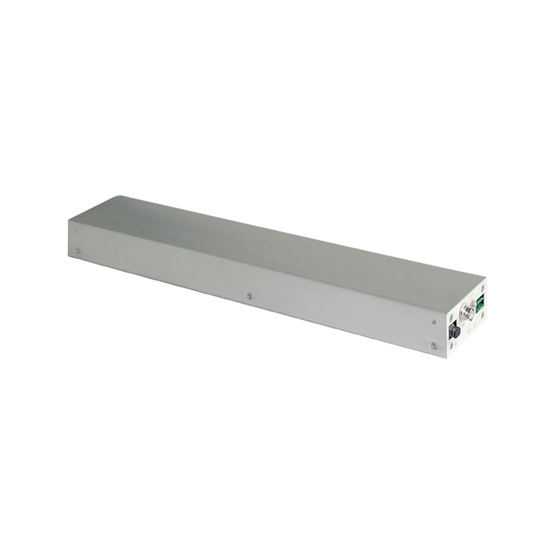
The high voltage power supplies for laser systems provide the energy for generating illumination pulses. Different laser types require different power supply characteristics. Flashlamp-pumped lasers require high voltage pulses to trigger the flashlamps. Q-switched lasers require high voltage pulses to operate the Q-switch. The power supply must generate pulses with appropriate amplitude, duration, and timing for the specific laser system.
Timing synchronization between multiple laser pulses requires precise control of the pulse generation timing. The time intervals between pulses must be controlled with accuracy sufficient for velocity measurement precision. Typical timing precision requirements range from nanoseconds to microseconds depending on the flow velocity and measurement requirements. The synchronization system must achieve this precision across multiple laser systems and pulse sequences.
Multi-laser system coordination involves synchronizing the operation of multiple laser units that may illuminate the flow from different directions or at different wavelengths. Each laser system has its own high voltage power supply and pulse generation electronics. The synchronization system must coordinate all units to generate pulses with the required timing relationships. The coordination must account for any timing offsets or delays inherent in each laser system.
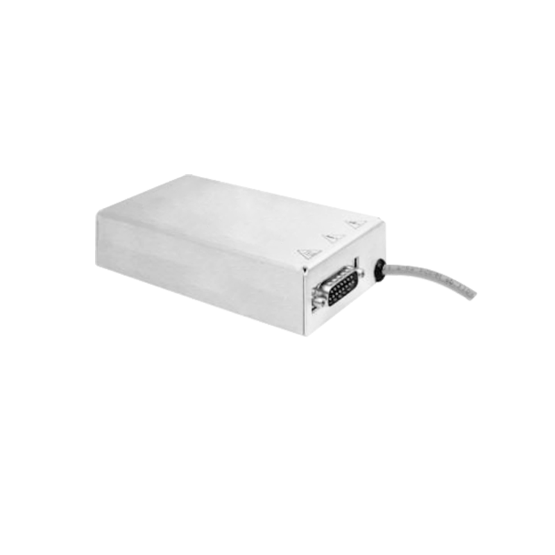
Timing distribution architectures deliver synchronization signals from a central timing controller to all laser power supplies. Electrical distribution networks transmit timing signals through cables, with propagation delays that must be accounted for in timing calculations. Optical distribution networks transmit timing signals through fiber optics, offering excellent noise immunity and precise timing propagation. The distribution architecture must maintain timing accuracy across all connected units.
Timing jitter in pulse generation affects the accuracy of velocity measurements. Jitter causes uncertainty in the actual time interval between illumination pulses, translating into velocity measurement uncertainty. The power supply and laser system must minimize jitter to achieve required measurement precision. Low-jitter triggering circuits and stable power supply operation reduce timing uncertainty.
Pulse energy consistency across multiple pulses affects the illumination quality and particle detection accuracy. Variations in pulse energy cause variations in image brightness that can affect particle detection algorithms. The power supply must generate pulses with consistent energy across the pulse sequence. Energy monitoring enables verification of pulse consistency.
Pulse shape characteristics affect the illumination duration and temporal resolution. Shorter pulse durations enable better temporal resolution but may require higher peak power for adequate illumination energy. The power supply must generate pulses with appropriate shape characteristics for the measurement requirements. Pulse shape monitoring enables verification of appropriate characteristics.
Thermal effects on timing precision arise from temperature-dependent delays in electronic components and laser systems. Temperature variations can cause timing drift that degrades synchronization accuracy. Temperature monitoring enables compensation for temperature-induced timing variations. Thermal management maintains stable operating temperatures for consistent timing performance.
Electromagnetic interference can affect timing circuits and cause timing errors or false triggers. The high voltage pulse generation creates electromagnetic noise that can couple into sensitive timing circuits. Shielding, filtering, and careful layout minimize interference effects on timing precision. The synchronization system must operate reliably in the electromagnetic environment created by laser operation.
Integration with camera systems requires coordination between laser illumination timing and camera exposure timing. The cameras must capture images synchronized with the laser pulses to record particle positions at the appropriate time instances. The synchronization system must generate timing signals for both lasers and cameras with appropriate relationships. Camera exposure timing must account for camera response characteristics.
Calibration procedures for synchronization systems verify timing accuracy and establish any necessary corrections. Timing measurements using fast photodiodes or other detectors characterize the actual pulse timing. Comparison of measured timing with commanded timing reveals any systematic offsets or errors. Calibration data enables correction of timing parameters for accurate synchronization.
Testing and verification of synchronization performance require specialized instrumentation and procedures. High-speed timing measurements characterize the timing precision across multiple pulse sequences. Long-duration testing verifies sustained timing accuracy over extended measurement sessions. Environmental testing verifies timing performance under various operating conditions.
Flow measurement validation verifies that synchronization accuracy translates into appropriate velocity measurement precision. Measurements of flows with known velocity fields enable verification of measurement accuracy. Statistical analysis of measurement results quantifies the velocity uncertainty attributable to timing precision. Validation confirms that synchronization meets measurement requirements.
Integration with flow measurement systems requires coordination between synchronization and other measurement functions. The synchronization system must operate within the overall measurement control architecture. Data acquisition must capture timing information along with image data for velocity calculation. System-level integration ensures that synchronization supports overall measurement capability.
Continued advancement in volume three-dimensional particle tracking velocimetry drives ongoing development of synchronization technology. Higher velocity measurements require better timing precision. Longer pulse sequences require more sophisticated timing coordination. Larger measurement volumes require coordination of more laser and camera systems. These evolving requirements ensure continued innovation in synchronization systems for advanced flow measurement applications.