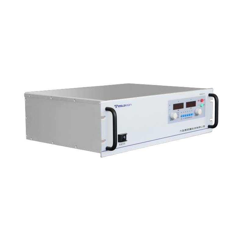
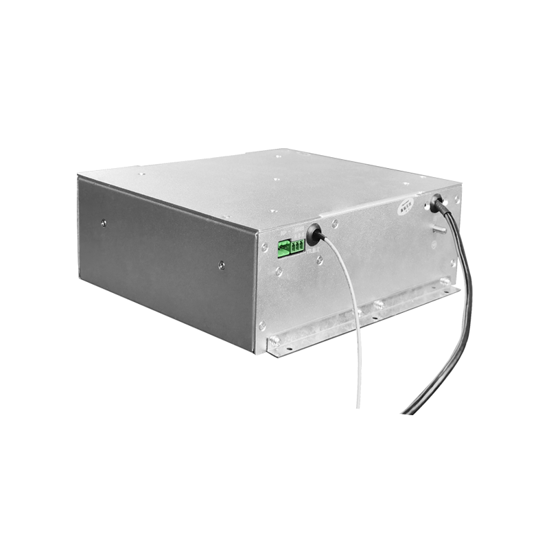
E-CHUCK High Voltage Power Supply Adsorption Force in Thin Film Transistor Manufacturing
The electrostatic chuck, commonly known as the E-CHUCK, has become an indispensable component in thin film transistor manufacturing processes, particularly in plasma-enhanced chemical vapor deposition, physical vapor deposition, and dry etching systems. The E-CHUCK uses electrostatic forces to hold semiconductor substrates firmly in place during processing, eliminating the mechanical clamping methods that can cause particle generation, substrate damage, and temperature non-uniformity. The high voltage power supply that energizes the E-CHUCK electrodes plays a critical role in determining the adsorption force, the substrate temperature control, and the overall process performance. The specific requirements of thin film transistor manufacturing impose demanding constraints on the E-CHUCK power supply design.
The E-CHUCK operates on the principle of electrostatic attraction between charged electrodes embedded in the chuck body and the substrate surface. The high voltage power supply applies a DC voltage, typically in the range of 500 V to 5 kV, between the electrodes and the substrate, creating an electrostatic force that holds the substrate against the chuck surface. The adsorption force is proportional to the square of the applied voltage and inversely proportional to the square of the gap between the electrode and the substrate. The power supply must deliver a precisely controlled voltage to achieve the required clamping force without exceeding the breakdown voltage of the dielectric layer that covers the electrodes.
The two primary types of electrostatic chucks used in thin film transistor manufacturing are the Coulombic type and the Johnsen-Rahbek type. The Coulombic chuck uses a thick dielectric layer with high resistivity, and the clamping force is generated by the Coulomb attraction between the charges on the electrode and the induced charges on the substrate. The Johnsen-Rahbek chuck uses a thin dielectric layer with a semiconductor-like resistivity, and the clamping force is enhanced by the Johnsen-Rahbek effect, which involves a small leakage current through the dielectric that creates a more efficient charge distribution. The high voltage power supply requirements differ between these two types, with the Johnsen-Rahbek chuck requiring a lower voltage but a more precise current limit.
The adsorption force of the E-CHUCK must be sufficient to hold the substrate against the forces exerted by the process gases, plasma, and mechanical handling. The required clamping force depends on the substrate size, the process pressure, and the specific process being performed. For a 300 mm silicon wafer in a typical plasma process, the clamping force required is on the order of 10 to 100 Newtons. The high voltage power supply must provide the voltage level necessary to generate this force while maintaining a safety margin to prevent the substrate from being released during processing. The power supply must also be capable of adjusting the voltage to compensate for variations in substrate thickness, resistivity, and surface condition.
The temperature control of the substrate during thin film transistor manufacturing is critical for achieving uniform film deposition and etching rates. The E-CHUCK serves as the primary thermal interface between the substrate and the temperature-controlled chuck body, with the adsorption force directly affecting the thermal contact conductance. A higher clamping force improves the thermal contact between the substrate and the chuck, enhancing the heat transfer and improving the temperature uniformity. The high voltage power supply must provide a stable voltage to maintain a consistent clamping force and thermal contact throughout the process, despite variations in the substrate temperature and the chuck temperature.
The high voltage power supply for the E-CHUCK must include precise current monitoring and limiting capabilities to protect the chuck and the substrate. The leakage current through the dielectric layer of the E-CHUCK is typically in the range of 1 microampere to 100 microamperes, depending on the chuck design and the operating conditions. The power supply must be able to measure this small leakage current accurately and to limit the output current to prevent damage to the dielectric layer. The current limit must be set to a value that is high enough to allow the chuck to charge up to the operating voltage within a reasonable time, but low enough to prevent dielectric breakdown in the event of a defect in the chuck or the substrate.
The polarity of the high voltage applied to the E-CHUCK electrodes can be positive, negative, or bipolar, depending on the chuck design and the process requirements. The bipolar chuck uses two electrodes with opposite polarities, creating a more uniform clamping force distribution and reducing the risk of charge buildup on the substrate. The high voltage power supply for a bipolar chuck must provide two independent outputs with opposite polarities, each with its own voltage regulation and current limiting. The voltage balance between the two electrodes must be maintained within tight tolerances to ensure uniform clamping across the entire substrate surface.
The dynamic response of the E-CHUCK power supply is important for the substrate handling sequence in thin film transistor manufacturing. The chuck must be charged to the operating voltage quickly after the substrate is placed on the chuck, and it must be discharged completely before the substrate is removed. The charging and discharging times are determined by the RC time constant of the chuck capacitance and the power supply output impedance. The power supply must be designed to charge the chuck capacitance within a few seconds without exceeding the current limit, and to discharge the chuck through internal bleed resistors or an active discharge circuit within a similar time frame.
The safety features of the E-CHUCK high voltage power supply are essential for protecting the equipment and the operators. The power supply must include overcurrent protection, overvoltage protection, and short-circuit protection that automatically shut down the output in the event of a fault. The output must be monitored continuously for leakage current and arc detection, with automatic shutdown if the leakage current exceeds a safe threshold. The power supply must also include a ground fault detection circuit that monitors the insulation resistance between the high voltage output and the ground and triggers an alarm if the insulation resistance falls below a specified value.
The integration of the E-CHUCK power supply into the thin film transistor manufacturing tool requires careful consideration of the electrical interface and the communication protocol. The power supply must be compatible with the tool control system, typically through a serial communication interface such as RS-232, RS-485, or EtherCAT. The communication protocol must support the exchange of control commands, status information, and diagnostic data between the power supply and the tool controller. The power supply must also provide analog or digital outputs for monitoring the voltage, current, and temperature, which can be used by the tool controller for process control and fault detection.
The reliability of the E-CHUCK power supply is critical for maximizing the uptime of the thin film transistor manufacturing tool. The power supply must be designed for continuous operation in the cleanroom environment, with adequate protection against the process gases, plasma radiation, and temperature variations. The power supply components must be selected for long life and high reliability, with derating margins applied to the voltage, current, and temperature ratings. The power supply must include self-diagnostic features that can detect impending failures and alert the maintenance personnel before a breakdown occurs.
The calibration and testing of the E-CHUCK power supply are essential for ensuring consistent process performance. The output voltage must be calibrated against a traceable standard at regular intervals, typically every six months or after any maintenance. The calibration procedure measures the actual output voltage at several points across the operating range and adjusts the power supply control parameters to correct any deviations. The leakage current measurement circuit must also be calibrated to ensure that the current limit and the fault detection thresholds are accurate. The chuck capacitance and the insulation resistance should be measured periodically to detect any degradation of the chuck dielectric properties.