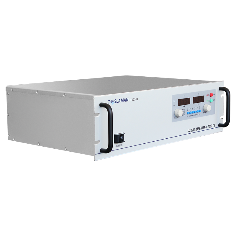
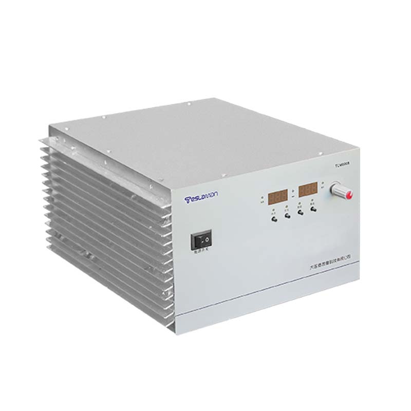
E-CHUCK High-Voltage Power Supply Adsorption in OLED Flexible Display and Advanced Packaging Technology
Electrostatic chuck adsorption in OLED flexible display and advanced packaging processes requires a supply that holds the substrate firmly while the temperature control operates underneath. The adsorption voltage sets the clamping force, and the force must be high enough to keep the substrate flat but low enough to avoid stress damage. The supply should regulate the clamping voltage precisely and respond quickly to the substrate changes.
The clamping force varies with the substrate material and the surface condition. A flexible display substrate deforms more than a rigid one, and the chuck must accommodate the deformation through the electrode zoning. The multi-zone control lets the clamping force be adjusted locally to match the substrate shape.
Temperature control in the process chamber interacts with the clamping: the heat transfer between the substrate and the chuck depends on the contact pressure, which is set by the clamping force. The supply and the temperature controller should be coordinated so that the clamping change does not disturb the temperature uniformity.
Fast clamping release is required when the substrate is transferred between stations, and the release speed is limited by the charge neutralization in the chuck dielectric. The supply should provide a fast discharge path so that the residual charge does not hold the substrate. The release time is measured during commissioning.
Arcing protection matters in a process chamber that contains reactive gases, because a particle can trigger an arc that damages the substrate edge. The supply should detect the arc and limit the arc energy within a short time. The arc counter data are used to monitor the chamber cleanliness.
The supply voltage range should cover the clamping needs of the substrate family processed by the tool. A wider range gives the process engineer the flexibility to optimize the clamping for each product. The range is defined during the tool specification phase.
Data logging from the chuck supply records the clamping voltage and the current during the process, which supports the diagnosis of substrate handling issues. A substrate that shifts position during the process often leaves a trace in the clamping current. The correlation between the logged data and the process events is established during commissioning.
Maintenance of the chuck supply covers the high-voltage cable, the connectors, and the chuck dielectric condition. The chuck dielectric wears with use, and the insulation resistance of the dielectric should be checked at planned intervals. The maintenance records are linked to the process chamber logs.
Operator training for the process tool covers the clamping parameter settings and the recognition of clamping faults. The operators should verify the clamping force before the process starts and respond to the alarms during the process. Training includes the safe discharge procedure before the chamber is opened.
The economic assessment of the chuck supply includes the substrate yield, the throughput, and the downtime. A supply that clamps reliably reduces the substrate loss from handling and processing. The yield gain across a production line justifies the investment in a high-performance chuck supply.
Periodic review of the equipment covers the performance, the maintenance, and the cost since the last review. The review findings are summarized into the recommendations for the next period. The review is scheduled annually or when a significant event occurs.
Commissioning of the supply begins with a visual inspection of the high-voltage section and the cooling path, followed by a no-load voltage check and a load test at the rated output. The acceptance data are recorded against the specification table, and any deviation is resolved before the equipment enters service. The commissioning report becomes the baseline for all later comparisons.
Acceptance testing covers the electrical performance, the protective functions, and the mechanical integrity. The test sequence is defined in the procurement document, and each test has a pass criterion. The signed acceptance record accompanies the equipment through the service life and supports the warranty claims when a defect appears.
Preventive maintenance scheduling follows the operating hours recorded by the supply itself. The maintenance tasks are grouped by interval, and the short-interval tasks are performed during the regular downtime windows. The long-interval tasks are planned into the annual shutdown. The maintenance history is kept with the equipment and reviewed when the interval policy is updated.
Calibration management covers the measurement channels used by the supply and the instruments used to verify the supply. Each channel has a calibration interval and a tolerance, and the calibration records are traceable to the laboratory standards. The calibration status is checked before a critical measurement campaign starts.
Environmental control in the equipment room stabilizes the operating conditions of the supply. The temperature and the humidity are monitored continuously, and the alarm thresholds are set to protect the insulation and the electronics. The environmental records are kept alongside the equipment log for the correlation analysis.
Data analysis turns the logged operating data into maintenance decisions. The voltage, current, temperature, and alarm trends are reviewed at planned intervals, and the deviations from the baseline trigger an investigation. The analysis report is shared with the engineering team and the maintenance crew.
Reliability assessment uses the field data collected from the equipment population. The failure rate, the repair time, and the availability are computed over a rolling period, and the results are compared with the design targets. The assessment output feeds the capital replacement plan and the spares strategy.
Energy efficiency of the supply affects the operating cost and the cooling load. The efficiency is measured at the representative operating points, and the improvement opportunities are evaluated against the implementation cost. The efficiency records are maintained for the lifetime comparison.
Reliability assessment uses the field data collected from the equipment population. The failure rate, the repair time, and the availability are computed over a rolling period, and the results are compared with the design targets. The assessment output feeds the capital replacement plan and the spares strategy.
Energy efficiency of the supply affects the operating cost and the cooling load. The efficiency is measured at the representative operating points, and the improvement opportunities are evaluated against the implementation cost. The efficiency records are maintained for the lifetime comparison.