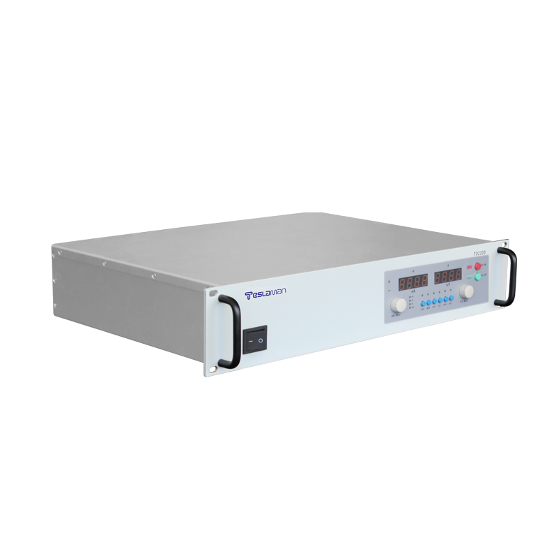
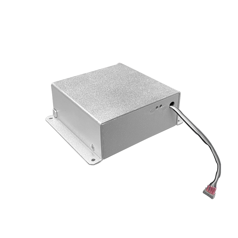
Standard Rack-Mounted High-Voltage Power Supply Integration in Edge Computing and Data Center High-Voltage Testing
Data center and edge computing facilities carry out high-voltage stress testing on power modules, insulation structures and distribution components as part of incoming inspection and periodic qualification. A standard rack-mounted high-voltage supply forms the core of such test benches because the unit delivers repeatable output across long test sessions and interfaces cleanly with automated logging systems. The rack format fits standard cabinets, and the front-panel layout keeps manual operation straightforward when a test sequence must be overridden.
Voltage accuracy matters more than raw range in acceptance testing. A 50 kV unit holding setpoint to plus or minus 0.1 percent eliminates ambiguity when a device under test sits near the specification limit. The feedback divider uses precision resistors with matched temperature coefficients, and the calibration offset is recorded in nonvolatile memory so the same correction applies after every power cycle.
Ripple performance determines whether the test reflects real operating conditions. High-frequency switching residue couples into measurement loops and produces false failures. The output filter is sized so residual ripple stays below the noise floor of the instrumentation, and the filter cutoff is placed below the lowest switching harmonic of the supply itself. Cable length and grounding layout receive the same attention as the supply specifications.
Load transients occur when a test item arcs or when a dielectric sample breaks down. The supply must recover from a momentary short without latching into fault state. Recovery time is measured with an electronic load that steps from ten percent to full rated current, and the control loop is tuned so overshoot stays below two percent while settling completes within several milliseconds. Repeated transient testing exposes weak damping in the compensation network.
Remote control becomes essential when the test bench is shared. The serial interface carries setpoint, readback and fault status, and the register map follows a published convention so third-party software can poll the unit without custom drivers. Watchdog behavior is defined for communication loss; the output holds the last valid setpoint and a local alarm sounds, which prevents silent shutdown during an unattended soak test.
Safety interlocks are part of the standard configuration. The high-voltage output is gated by an external contact loop, so a test chamber door or an emergency stop button can remove the output regardless of the software state. The interlock path is kept fully hardwired, and the contact rating is verified against the discharge current that flows when the output is dumped.
Thermal management in a shared cabinet deserves review. Several supplies mounted in one rack raise the inlet temperature for units above the lower row. The cooling fans ramp with internal temperature, and derating curves are published so the operator can calculate the maximum duty cycle when ambient air exceeds thirty-five degrees. Filter cleaning is scheduled on a calendar basis because clogged filters silently degrade derating margins.
Calibration discipline keeps long-term results trustworthy. A yearly verification against a calibrated divider checks both voltage accuracy and ripple at three output points. The verification records are stored with the test logs, and drift beyond the published tolerance triggers a repair action before the unit returns to service. Preventive maintenance therefore stays aligned with measurement confidence.
Commissioning of the supply starts with a visual inspection of the high-voltage section and the cooling path, followed by a no-load voltage check and a load test at the rated output. The acceptance data are recorded against the specification table, and any deviation is resolved before the equipment enters service. The commissioning report becomes the baseline for all later comparisons.
Acceptance testing covers the electrical performance, the protective functions, and the mechanical integrity. The test sequence is defined in the procurement document, and each test has a pass criterion. The signed acceptance record accompanies the equipment through the service life and supports the warranty claims when a defect appears.
Preventive maintenance scheduling follows the operating hours recorded by the supply itself. The maintenance tasks are grouped by interval, and the short-interval tasks are performed during the regular downtime windows. The long-interval tasks are planned into the annual shutdown. The maintenance history is kept with the equipment and reviewed when the interval policy is updated.
Calibration management covers the measurement channels used by the supply and the instruments used to verify the supply. Each channel has a calibration interval and a tolerance, and the calibration records are traceable to the laboratory standards. The calibration status is checked before a critical measurement campaign starts.
Documentation control ensures that the drawings, the manuals, and the configuration records reflect the installed equipment. Any modification is documented with the change reason and the verification result. The document set is reviewed at planned intervals, and the obsolete versions are archived rather than discarded.
Spare parts management matches the stock level to the failure statistics of the equipment family. The fast-moving parts are kept on site, and the slow-moving parts are sourced on demand. The stock review is performed quarterly, and the review data include the part cost and the delivery lead time.
Safety procedures around the high-voltage equipment are written, reviewed, and rehearsed. The procedures cover the access control, the discharge sequence, and the use of personal protective equipment. The rehearsal results are recorded, and the procedure is revised when the rehearsal reveals a gap.
Environmental control in the equipment room stabilizes the operating conditions of the supply. The temperature and the humidity are monitored continuously, and the alarm thresholds are set to protect the insulation and the electronics. The environmental records are kept alongside the equipment log for the correlation analysis.
Data analysis turns the logged operating data into maintenance decisions. The voltage, current, temperature, and alarm trends are reviewed at planned intervals, and the deviations from the baseline trigger an investigation. The analysis report is shared with the engineering team and the maintenance crew.
Reliability assessment uses the field data collected from the equipment population. The failure rate, the repair time, and the availability are computed over a rolling period, and the results are compared with the design targets. The assessment output feeds the capital replacement plan and the spares strategy.
Energy efficiency of the supply affects the operating cost and the cooling load. The efficiency is measured at the representative operating points, and the improvement opportunities are evaluated against the implementation cost. The efficiency records are maintained for the lifetime comparison.