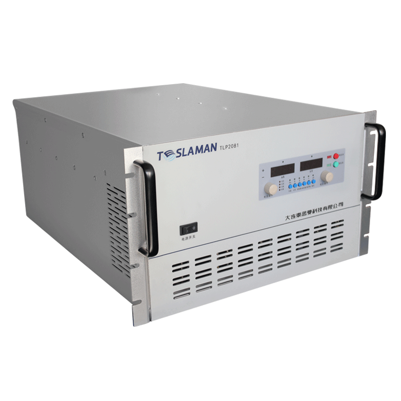
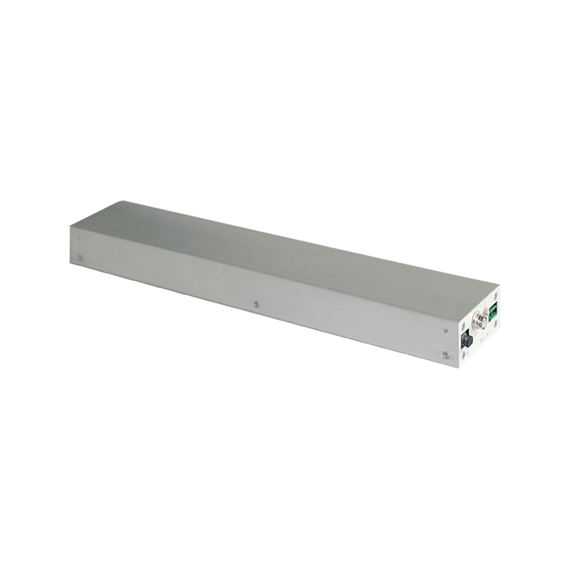
Lithography High-Voltage Power Supply Key Powering Technology in Advanced Nodes and EUV-Assisted Processes
Advanced lithography nodes place extreme demands on the powering of the illumination and stage systems, and the high-voltage supply that feeds the light source must deliver stability that the optical system takes for granted. EUV-assisted processes add further constraints because the source and the optics tolerate almost no energy fluctuation.
The light source converts electrical energy into a plasma or a discharge, and the energy per pulse sets the exposure dose. Pulse-to-pulse energy variation must stay below the value that the process latitude allows, so the supply charges the storage capacitors to a tightly regulated voltage and discharges the capacitors through a controlled switch with minimal timing jitter.
Voltage regulation accuracy on the charging stage determines the energy repeatability. The charge loop measures the capacitor voltage with a precision divider and terminates the charge when the setpoint is reached; a stable reference and a low-noise measurement path keep the termination error small, and the residual variation is characterized at the factory and documented for the integration team.
Switch timing jitter broadens the energy distribution of the pulses. The discharge switch is driven by a low-jitter trigger chain, and the supply layout keeps the trigger path short and shielded. Measurements of the delivered pulse train show that the combination of voltage accuracy and timing stability holds the dose within the specification across a full exposure sequence.
EUV-assisted processes run at high repetition rates, and the supply must recharge the storage bank between pulses. The charging power stage is sized so that the recharge completes within the inter-pulse interval, and the regulation loop settles before the next discharge command arrives. Any shortfall in charging power shows up as a droop in the pulse energy over the burst.
Thermal management of the charging and switching stages is critical at high duty cycles. The switching losses and the charging losses heat the cabinet, and the cooling system must hold the component temperatures within the derating envelope over an entire production shift. Temperature-compensated reference circuits keep the energy setpoint stable while the cabinet warms.
Arcing or misfiring in the source must not damage the supply. The protection chain detects an abnormal discharge and interrupts the charging cycle, while the stored energy is dumped through a controlled bleed path. The recovery sequence is fast enough that the production tool resumes within the allowed downtime window.
Serviceability matters for a tool that runs around the clock. The supply is built from replaceable assemblies, and the fault diagnostics identify the failing stage from the event log. Spare modules and a documented exchange procedure keep the repair time short, and the maintenance records track component aging for predictive replacement.
Safety procedures around the high-voltage equipment are written, reviewed, and rehearsed. The procedures cover the access control, the discharge sequence, and the use of personal protective equipment. The rehearsal results are recorded, and the procedure is revised when the rehearsal reveals a gap.
Environmental control in the equipment room stabilizes the operating conditions of the supply. The temperature and the humidity are monitored continuously, and the alarm thresholds are set to protect the insulation and the electronics. The environmental records are kept alongside the equipment log for the correlation analysis.
Data analysis turns the logged operating data into maintenance decisions. The voltage, current, temperature, and alarm trends are reviewed at planned intervals, and the deviations from the baseline trigger an investigation. The analysis report is shared with the engineering team and the maintenance crew.
Reliability assessment uses the field data collected from the equipment population. The failure rate, the repair time, and the availability are computed over a rolling period, and the results are compared with the design targets. The assessment output feeds the capital replacement plan and the spares strategy.
Energy efficiency of the supply affects the operating cost and the cooling load. The efficiency is measured at the representative operating points, and the improvement opportunities are evaluated against the implementation cost. The efficiency records are maintained for the lifetime comparison.
Training programs for the operating and maintenance staff are scheduled at defined intervals. The training covers the safe operation, the routine checks, and the fault diagnosis flow. The training effectiveness is verified with a written test and a practical exercise, and the results are filed with the personnel records.
Process qualification is performed whenever the equipment or the process recipe changes. The qualification plan defines the test articles, the acceptance criteria, and the data to be recorded. The qualification report is approved before the new condition enters production.
Failure analysis follows a defined path from the symptom to the root cause. The analysis uses the logged data, the physical evidence, and the repair records. The analysis conclusion is documented with the corrective action, and the corrective action is verified after implementation.
Quality records link the equipment performance to the product quality. The operating parameters and the product measurements are filed together, so that a product deviation can be traced to the equipment condition. The record retention period follows the regulatory and contractual requirements.
Vendor coordination covers the technical support, the spare supply, and the repair service. The service level agreement defines the response time and the repair turnaround. The vendor performance is reviewed periodically, and the review outcome influences the future procurement decisions.
Continuous improvement is driven by the analysis of the failure data and the operating experience. Each improvement proposal is assessed for the benefit, the cost, and the risk before implementation. The implemented improvements are tracked for the realized benefit.
Operator handover between shifts includes the equipment status, the pending issues, and the instructions for the current operation. The handover log is signed by both parties, and the entries are concise and factual. The handover discipline maintains the continuity of the operation.
Performance monitoring covers the key parameters that indicate the health of the supply. The monitoring points and the thresholds are defined during commissioning, and the measured values are recorded on a regular basis. The monitoring data support the early detection of the degradation trends.
Long-term stability of the supply is verified by the periodic re-measurement of the output characteristics. The measurements are compared with the baseline recorded at acceptance, and the drift trend is analyzed. A drift beyond the tolerance triggers a detailed investigation and a corrective action.