Standardization of Rack-Mounted High-Voltage Power Supply for Accelerator and Mass Spectrometry Platforms
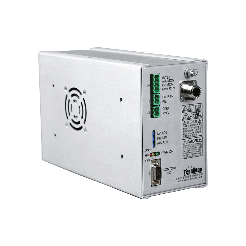
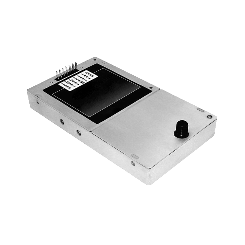
Standardization of a rack-mounted supply for accelerator and mass spectrometry platforms addresses the repeatable integration across the instrument population. The same supply platform serves different instruments, the interface and the performance are unified, and the standardization reduces the commissioning and the maintenance effort.
The mechanical interface is standardized. The rack dimensions, the mounting and the connector positions follow the common layout, the cable routing is defined, and the replacement of the unit requires no mechanical rework.
The electrical interface is unified. The control signals, the status outputs and the interlocks use the common definition, the communication protocol is consistent, and the instrument integration follows the standard wiring diagram.
The performance specification is shared. The voltage accuracy, the ripple and the response are defined in the common document, the acceptance test follows the standard procedure, and the measured data is comparable across the units.
Calibration is supported by the standard procedure. The voltage and the current channels are verified with the same reference, the correction table format is unified, and the calibration record is compatible with the platform.
Spare management benefits from the standardization. The common modules are stocked, the failure rate data is pooled, and the replacement decision is based on the aggregated statistics.
Firmware and the parameter set are version controlled. The upgrade is tested on the platform, the field update follows the standard procedure, and the rollback plan is part of the release.
Field experience across the instruments feeds back into the platform improvement. The common failure modes are addressed in the next revision, the improvement is verified, and the platform evolves without breaking the installed base.
Transport and storage of a high-voltage supply carry separate requirements. The vibration and the shock during the transport may damage the devices, the storage temperature and humidity affect the insulation material, and the incoming inspection checks the list and the appearance.
Abnormal sound and smell are the early hints of a fault. The transformer hum change and the device heating smell relate to the internal state, the patrol pays attention to these signs, and the serious fault often has the precursor.
On-site spare replacement uses the parts meeting the specification. The substitute parameters are checked item by item, the voltage class and the current capability are not lowered, the part source is reliable, and the performance verification after the replacement is not skipped.
Debugging tools of a high-voltage supply are calibrated regularly. The high-voltage attenuation ratio of the probe and the accuracy of the meter affect the judgment, the tool state is confirmed before the use, and the misjudgment from the measurement error wastes a lot of the searching time.
Lightning and overvoltage protection combines with the installation environment. The protection requirement is higher in the lightning-prone area, the surge protection device at the input is checked regularly, and the cause is found after the device action instead of a simple reset.
Operating record of a high-voltage supply is continuous and complete. The stop reason, the running time and the fault handling are recorded, the continuous accumulation supports the state assessment, and the interrupted period is noted with the reason.
Poor contact in the high-voltage circuit is easily overlooked. The heating at the connection indicates the increased contact resistance, the connection temperature is checked regularly with the infrared aid, and the abnormal contact state is handled immediately.
Evaluation before the equipment modification is adequate. The modification goal, the affected scope and the verification method are defined, the risk during the modification is identified in advance, and the verification after the completion covers the key indicators.
Field commissioning of a high-voltage supply exposes most of the hidden problems. The load nature, the cable length and the grounding arrangement all change the actual output behavior, so the commissioning record must be kept complete and every parameter change tied to the concrete condition.
Insulation coordination must be verified early in the commissioning phase. The withstand test and the partial discharge test results are archived, the difference between the test condition and the field condition is assessed separately, and the insulation margin is checked against the worst case.
High-voltage wiring affects the performance far more than ordinary low-voltage wiring. The output cable capacitance changes the dynamic response, the shield termination changes the noise level, and the routing path should be fixed once verified.
Protection threshold settings must follow the actual load characteristics. A threshold set too low trips on normal fluctuation, while a threshold set too high loses the protection meaning, so the setting process relies on the historical data and separates the start-up surge from the real fault.
Temperature effects on a high-voltage supply are often underestimated. Device parameters drift with temperature, insulation performance changes with temperature, and the cooling condition changes with the season, so the ambient temperature monitoring belongs in the routine inspection.
Output deviation after long operation needs a distinction between the systematic drift and the random fluctuation. The systematic drift points to the reference or the sampling chain, while the random fluctuation often relates to interference or contact state, and the judgment comes from the calibration records.
Fault handling on site follows the sequence of isolate first and investigate after. The first step after a fault is to remove the high voltage and confirm the discharge, then the input, the power stage, the sampling chain and the load are checked in order.
Electromagnetic compatibility problems are common in high-voltage equipment. The switching action of the power stage couples into the control circuit through the parasitic path, and the shielding and the grounding treatment decide the interference level, so the on-site diagnosis relies on the waveform record.
Grounding system handling is a key part of the high-voltage installation. The ground reference of the high-voltage side and the low-voltage side must be clear, the shield grounding choice between the single point and the multi point depends on the interference frequency, and the ground check belongs in the regular maintenance.
Component aging patterns form the basis of the maintenance schedule. The electrolytic capacitor capacitance decays with temperature and energizing time, the contact wear relates to the operation count, and the fan life depends on the running hours, so the maintenance plan follows the actual operating data.
Efficiency of a high-voltage supply differs clearly across the load points. The fixed loss share is high at light load, the conduction loss rises at full load, and the efficiency curve must be measured at several load points with the measurement condition stated in the documentation.