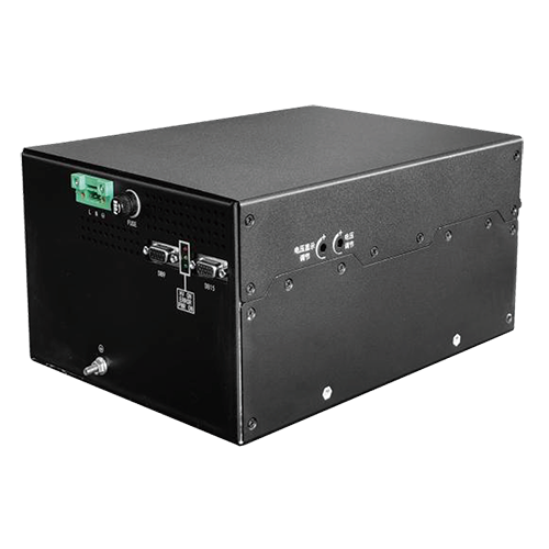
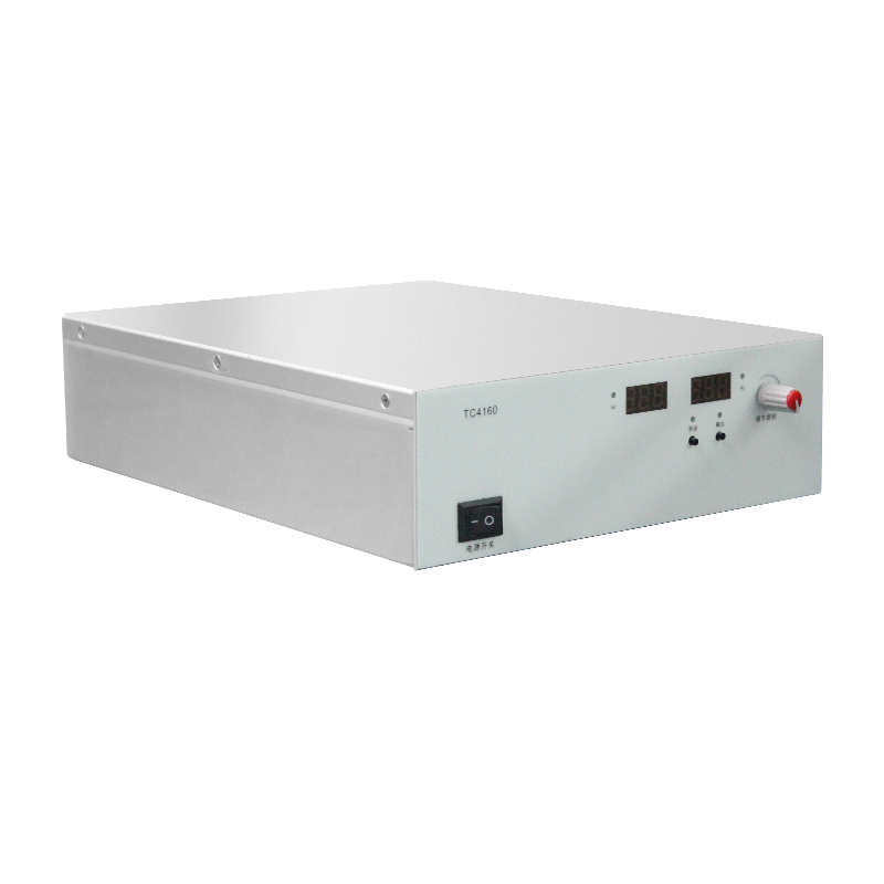
Waveform Design of Coating Pulsed High-Voltage Power Supply Dynamic Response in Functional Thin Film Preparation
The waveform design of a coating pulsed supply in functional thin film preparation shapes the discharge for the film property. The pulse parameters define the ion energy and the deposition condition, the supply generates the defined waveform, and the film result verifies the design.
The pulse voltage sets the discharge energy. The peak voltage is calibrated, the pulse width is controlled, and the energy input is repeatable per pulse.
The pulse frequency sets the deposition rate. The frequency and the duty cycle balance the rate and the heat, the supply holds the timing, and the film thickness is uniform.
The waveform edge defines the arc behavior. The rise and the fall are controlled, the arc is suppressed at the edge, and the defect density is reduced in the film.
The pulsed and the continuous mode are switchable. The recipe defines the mode per process step, the switching is smooth, and the film stack quality is verified.
The dynamic response of the supply follows the pulse load. The energy storage supports the pulse, the voltage droop is limited, and the pulse shape is maintained across the run.
Process verification uses the film measurement. The thickness, the stress and the optical property are measured, the data is compared with the target, and the waveform is adjusted from the result.
Field maintenance focuses on the pulse circuit. The capacitor and the switch condition are checked, the waveform is monitored, and the maintenance follows the trend data.
The soft start circuit limits the inrush at the power-up. The starting resistor and the bypass relay work together, the bus voltage rises smoothly, and the inrush current stays below the rated limit.
The output filter is arranged for the ripple requirement. The equivalent series resistance of the capacitor controls the high-frequency attenuation, the resonance peak is damped, and the ripple is measured at the load terminal.
The thermal design follows the loss calculation. The conduction and the switching losses define the dissipation, the heat sink matches the thermal resistance, and the temperature rise test confirms the margin.
The protection logic is layered. The hardware comparator acts fast, the software logic confirms the event, and the recovery requires the manual reset after the cause is cleared.
Electromagnetic compatibility is handled at the structure level. The shield covers the sensitive section, the cable shield is terminated at one point, and the conducted and the radiated tests follow the standard procedure.
Long-term stability is maintained by the periodic measurement. The output voltage and the current are compared with the baseline, the drift trend is recorded, and the component aging is predicted from the data.
Commissioning follows the fixed sequence. The low-voltage test comes first, the high-voltage test follows, the load is increased in steps, and each protection action is verified before the next step.
The high-voltage cable is selected for the voltage and the current. The insulation thickness meets the withstand requirement, the bending radius fits the installation, and the routing avoids the heat source and the mechanical damage.
The current sampling accuracy depends on the shunt and the amplifier chain. The shunt is selected for the low temperature coefficient, the gain is calibrated, and the filtered signal enters the control loop.
The voltage establishment time is set by the load capacitance. The charging current is limited by the current limit, the establishment time scales with the stored energy, and the production cycle verifies the setting.
The high-voltage rectifier uses the series structure. The equalizing resistor matches each diode, the reverse recovery is consistent, and the voltage distribution is verified by the measurement.
The voltage divider precision affects the feedback quality. The temperature coefficient is compensated, the insulation support avoids the leakage shunt, and the calibration uses the traceable reference.
The gate drive is designed for the switching loss and the reliability. The drive voltage saturates the switch, the negative bias suppresses the false trigger, and the gate resistance matches the switching speed.
The high-voltage module equalizing design keeps the series voltage balanced. The equalizing resistor shunts the module, the unbalance stays within the limit, and the measured distribution confirms the design.
The ripple and the dynamic performance are a trade-off. The stronger filter reduces the ripple, the limited loop bandwidth slows the response, and the setting follows the application priority.
The protection threshold is set from the operating condition. The overvoltage threshold sits above the highest running voltage, the overcurrent threshold sits below the dangerous current, and the delay avoids the normal transient.
The insulation material is selected for the voltage and the temperature. The dielectric strength carries the margin, the thermal class matches the operating temperature, and the aging data supports the life assessment.
The control loop stability is verified by the phase margin. The compensation is set at the crossover frequency, the step response shows no oscillation, and the recovery time meets the load change requirement.
The high-voltage terminal design controls the discharge risk. The electrode chamfer reduces the field concentration, the insulation distance follows the withstand calculation, and the partial discharge test verifies the structure.
The efficiency depends on the topology and the device loss. The soft switching reduces the switching loss, the magnetic design optimizes the copper and the core loss, and the efficiency is measured at several load points.
The high-voltage switching sequence follows the safety order. The shutdown comes before the discharge, the discharge completion is confirmed, and the maintenance is permitted only after the confirmation.
The temperature sampling covers the critical device positions. The sensor layout follows the thermal analysis, the channels are calibrated, and the derating control uses the temperature data.
The galvanic isolation serves the insulation and the signal transfer. The optical isolation converts the low-voltage signal, the withstand voltage meets the standard, and the isolation performance is verified periodically.
The digital control keeps the hardware safety baseline. The hardware protection is independent of the software, the fast shutdown does not depend on the program state, and the abnormal path is verified.
The startup check covers the grounding and the interlock state. The ground resistance is confirmed, the interlock loop is tested, and the discharge path is verified before the power-up.
The ripple measurement excludes the external interference. The probe is grounded locally, the shield is complete, the bandwidth matches the indicator, and the repeated measurement is averaged.