







Multiple Voltages of Electrospinning High-Voltage Power Supply in Tissue Regeneration Scaffold and Smart Textile
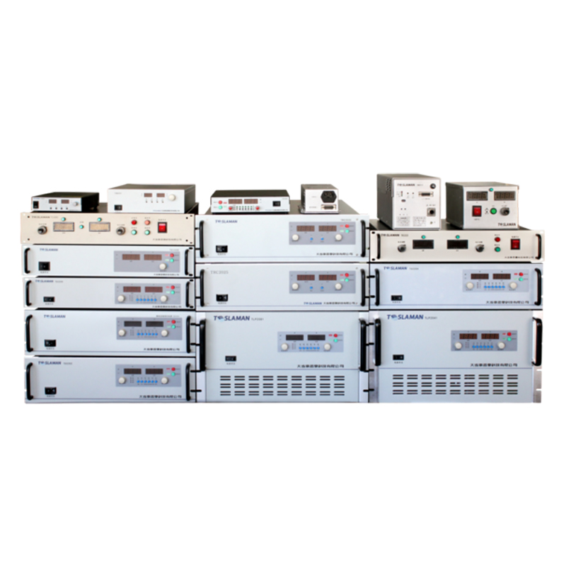
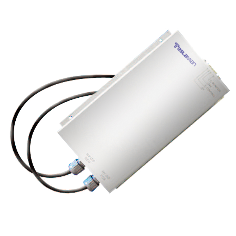
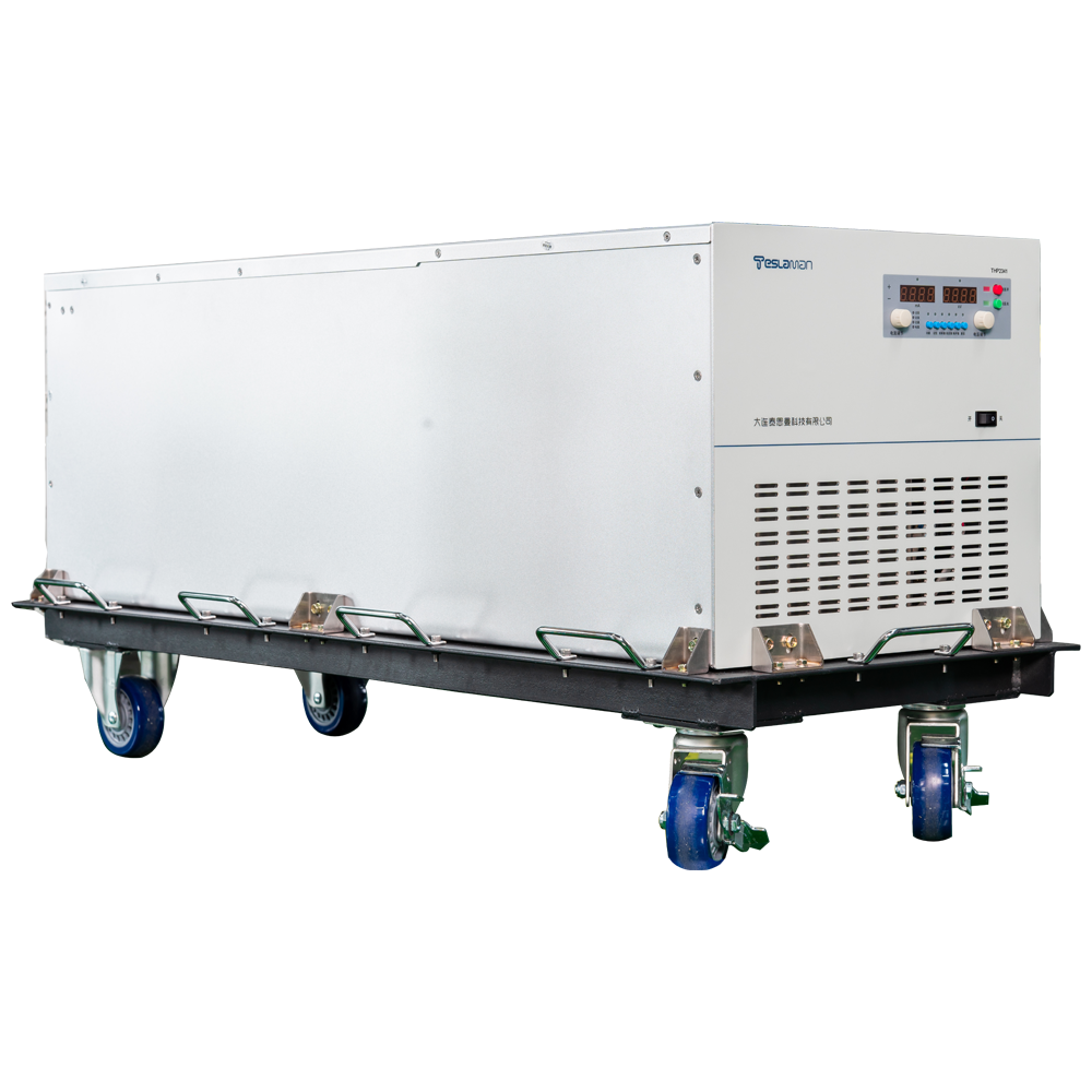
The multiple voltages of an electrospinning supply in tissue regeneration scaffold and smart textile keep the fiber uniform across the deposition area. The scaffold and the textile depend on the repeatable field, so the supply holds the multi-channel voltage and the fiber result is verified by the density measurement.
The multi-channel output covers the deposition area. The channels are isolated, the field distribution is even, and the fiber density is uniform.
The voltage range covers the process window. The low voltage for the fine fiber, the high voltage for the thick fiber, and the switching follows the recipe.
The fiber diameter control depends on the voltage and the flow match. The flow rate and the field are coordinated, the diameter is repeatable, and the scaffold porosity is maintained.
The current limit protects the collector and the operator. The current is bounded, the arc condition is handled, and the operation resumes after the confirmation.
The environment affects the spinning repeatability. The humidity and the temperature are compensated, the voltage window is verified, and the seasonal variation is handled.
The process verification uses the fiber measurement. The diameter and the density are compared with the target, and the voltage is adjusted from the result.
Field maintenance focuses on the high-voltage chain and the nozzle state. The fiber result is verified periodically, and the anomaly is located from the record.
The charge current and the charge time are a trade-off. The large current refills fast but stresses the grid, and the compromise follows the field supply capacity.
The magnetic loss is measured by the power meter. The difference between the input power and the output power is the loss, and the meter accuracy decides the loss judgment.
The saturation of the core is observed from the current waveform. The obvious distortion of the current waveform indicates the approaching saturation, and the waveform monitoring is more direct than the theoretical estimate.
The winding arrangement of the high-frequency transformer decides the distributed capacitance. The small layer distance gives the large capacitance, and the trade-off between the insulation distance and the capacitance follows the application.
The leakage compensation of the transformer balances the efficiency. The over-compensation adds the loss, the under-compensation distorts the waveform, and the value is tuned from the waveform measurement.
The insulation test of the transformer follows the standard flow. The withstand test and the insulation resistance test are done separately, the conditions differ, and the mixed result is not reliable.
The input current waveform of the PFC is observed on the oscilloscope. The high distortion gives the large harmonic, and the measured waveform guides the parameter adjustment.
The resonance point of the input filter avoids the working frequency. The filter resonance amplifies the specific frequency interference, and the resonance frequency is designed outside the switching frequency.
The efficiency curve of the wide input range has the valley. The efficiency drops when the input deviates from the nominal value, and the full-range evaluation is weighted by the actual voltage distribution.
The transition of the constant-voltage constant-current switch is smooth. The overshoot of the voltage and the current during the switch damages the load, and the switch logic is verified on the oscilloscope.
The long-term output accuracy relies on the periodic calibration. The reference drift is the main cause of the accuracy drop, and the calibration interval matches the drift rate.
The micro-current measurement demands the shielding and the insulation. The leakage and the space interference affect the reading, and the insulation and the shield of the path are handled first.
The temperature drift of the current sense resistor affects the accuracy. The large current heats the resistor, the resistance drifts, and the compensation or the low-drift selection follows.
The resolution of the high-precision setting conflicts with the noise. The high resolution gives the visible step noise, and the stepping method and the filter are matched.
The load line characteristic is decided by the output impedance. The high impedance gives the poor load regulation, the low impedance affects the stability, and the value follows the load type.
The transient control of the mode switch uses the ramp. The sudden change of the output parameter causes the overshoot, the ramp or the rate limit is added, and the transient is controlled.
The abnormal record during the test has the same value. The phenomenon, the action and the recovery are recorded, and the abnormal record is the material for the design improvement.
The first power-on check follows the fixed order. The wiring is checked before the power, the low voltage before the high voltage, the no-load before the loaded, and the reversed order causes the accident.
The parameter change during the field debug is kept. The content, the reason and the effect of the change are recorded, and the rollback and the trace are supported.
The re-test after the transport is not skipped. The vibration loosens the fastener and shifts the component, and the re-test items match the factory acceptance.
The long-running equipment gets the periodic inspection. The temperature, the noise, the vibration and the drift are recorded, the trend is built, and the anomaly is found early.
The test fixture life is managed. The worn fixture shifts the test result, the fixture is replaced by the count or the period, and the calibration verifies the state.
The environment condition during the test is recorded. The temperature and the humidity affect the insulation and the accuracy result, and the condition is written into the report.
The report conclusion corresponds to the data. The conclusion is derived from the data, the conclusion is not made from the incomplete data, and the data integrity is checked first.
The operator training follows the standard work instruction. The step, the criterion and the abnormal handling are consistent with the actual action.
The traceability system manages by the batch. The test data of each unit is linked to the serial number, and the problem is traced back to the specific batch and stage.
The field measurement of the power factor requires the calibrated wattmeter. The wattmeter is verified against the standard source, and the measured value is compared with the calculated value.
The load regulation measurement is done at the defined load step. The output change between the no-load and the rated load is recorded, and the regulation value is judged against the specification.