









Field penetration of 450 kV high-voltage power supplies in on-site non-destructive testing of ship welds and pressure vessels
A 450 kV portable X-ray supply is used for field non-destructive testing of ship welds and pressure vessels. The supply is housed in a 20 kg aluminum case, 400 mm by 300 mm by 200 mm, with a carrying handle. The X-ray tube is a directional type, 450 kV at 5 mA, with a 5 mm focal spot. The tube is oil insulated, with a 5 L oil volume. The supply runs from a 230 V single phase generator, 3 kW capacity.
The X-ray beam is collimated to a 30 degree cone, and the exposure time is set from 0.1 seconds to 10 minutes. The film is a type C4, 100 mm by 300 mm, placed behind the weld. The source to film distance is 1 m, and the exposure is calculated from the material thickness and the film speed. A 20 mm steel weld requires 5 minutes at 450 kV and 5 mA. The exposure is verified by a step wedge, placed on the film alongside the weld.
The high-voltage inverter runs at 20 kHz, with a 540 V DC bus. The transformer is a 1:100 step-up, oil insulated, and the rectifier is a voltage multiplier chain that brings the output to 450 kV. The output ripple is 1 percent peak to peak, at 1200 Hz. The ripple is measured by a high-voltage divider, and the reading is displayed on the supply front panel.
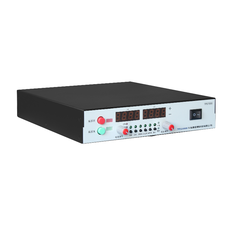
The supply control panel has a voltage knob, a current knob, a timer, and an exposure button. The voltage is adjustable from 0 to 450 kV, in 1 kV steps. The current is adjustable from 0 to 5 mA, in 0.1 mA steps. The timer is adjustable from 0.1 seconds to 10 minutes, in 0.1 second steps. The exposure button is a two-stage type, with a preparatory position and an exposure position. The preparatory position warms up the filament, and the exposure position starts the X-ray output.
The field operation requires a radiation safety officer, who monitors the dose rate around the exposure area. The officer sets up a radiation boundary, 10 m from the source, and posts warning signs. The officer wears a film badge, and the badge is read out monthly. The dose rate at the boundary is measured with a survey meter, and the reading must stay below 2.5 μSv per hour.
The supply cooling is natural convection, with cooling fins on the oil tank. The oil temperature reaches 50 degrees after 10 minutes of continuous exposure, against an ambient of 25 degrees. The oil temperature is monitored by a thermal switch, and the supply shuts down if the temperature exceeds 70 degrees. The silica gel breather on the oil tank changes color after 6 months, and the gel is replaced before the color reaches half saturation.
The X-ray tube filament is heated to 2000 degrees, and the filament life is 500 hours. The filament is a tungsten wire, 0.5 mm diameter. The filament power supply is a 5 V, 10 A unit, integrated inside the supply case. The filament current is monitored, and a 10 percent increase in filament current signals end of filament life.
The safety interlock on the exposure button was tested during commissioning. The two-stage button requires deliberate action, and a single press does not start the exposure. The preparatory position warms up the filament for 5 seconds, and the exposure position starts the X-ray output. The button is mounted on a 2 m cable, so the operator can stand behind a shield during exposure. The exposure stops when the button is released, or when the timer expires.
The maintenance log lists routine tasks. Each shift, the operator records the exposure parameters and the oil temperature. Weekly, the technician inspects the cable jacket and the cooling fins. Monthly, the insulation resistance is measured with a 2500 V megohmmeter, and the reading should exceed 1000 MΩ. Quarterly, the divider is calibrated against a 0.1 percent standard. Annually, the tube output is verified with a radiation detector. The log is signed at each step, and the record is filed in the service archive.
The input side of the supply draws 230 V single phase at 10 A, from a portable generator. The generator is a 3 kW gasoline type, with a 10 L fuel tank. The generator runs for 4 hours on a full tank, and the fuel consumption is 2.5 L per hour. The generator output voltage is held at 230 V plus or minus 5 percent by an automatic voltage regulator. The input cable is copper, 2.5 mm², rated for 16 A, with a CEE plug. The input breaker is a 16 A miniature type, with a thermal-magnetic trip. The input power factor is 0.95, measured with a power analyzer during commissioning.
The high-voltage transformer inside the supply case is oil insulated, with a 5 L oil volume. The oil temperature reaches 50 degrees after 10 minutes of continuous exposure at 450 kV and 5 mA, against an ambient of 25 degrees. The silica gel breather on the oil tank changes color after 6 months, and the gel is replaced before the color reaches half saturation. The oil breakdown voltage is tested annually, and the last measurement showed 38 kV per 2.5 mm gap, well above the 25 kV replacement threshold. The transformer sound level is 55 dB at 1 m, measured with a sound level meter during commissioning.
The output divider is a series chain of 100 MΩ high-voltage glass glaze resistors, totaling 4 GΩ. The divider tap at 1:4000 feeds the control board ADC. The divider is calibrated quarterly against a 0.1 percent standard divider. The calibration drift over 12 months was 0.4 percent, equivalent to 1.8 kV at 450 kV. The drift is within the 1 percent acceptance limit, but the divider is scheduled for resistor replacement at the 24 month mark.
The X-ray tube window is a beryllium foil, 1 mm thick, sealed to the tube body with a gold O-ring. The window transmits the X-ray beam, and the foil erodes slowly over 500 hours of exposure. The window once developed a pinhole leak, and the tube vacuum dropped from 1e-4 Pa to 1 Pa. The tube was replaced, and the new tube was run in for 10 hours at half power. The window integrity is checked monthly, by measuring the tube vacuum.
The field test procedure is written in the service manual. The service crew arrives at the shipyard or pressure vessel site, sets up the radiation boundary, positions the supply, and makes the exposure. The film is developed in a portable darkroom, and the radiograph is interpreted by a certified inspector. The test report is written on site, and the customer signs the report before the crew leaves. The entire procedure takes 2 hours per weld, including setup and teardown.
The customer acceptance test was run over two days. Day one covered the ship weld testing, on a 20 mm steel plate, at 450 kV and 5 mA. Day two covered the pressure vessel testing, on a 30 mm steel plate, at 450 kV and 5 mA. The test report was signed by the customer representative, and the supply entered the 12 month warranty period.
The field environment around the supply is uncontrolled, with ambient temperature ranging from 5 to 35 degrees Celsius. Winter operation at 5 degrees requires the supply to warm up for 10 minutes before exposure, because the oil viscosity rises and the transformer efficiency drops. Summer operation at 35 degrees requires the supply to be shaded from direct sun, because the oil temperature reaches 60 degrees in direct sun. The service crew carries a sun shade in the supply case. The humidity ranges from 30 to 90 percent, and the supply has IP54 protection, with the case sealed against rain.
The service crew consists of two technicians, certified in non-destructive testing and radiation safety. The crew carries the supply, the generator, the survey meter, and the film badges in a service van. The van is stocked with spare parts, tools, and personal protective equipment. The crew responds to service calls within 24 hours, and the typical job takes 4 hours, including travel time. The service record is filed in the service archive, and the customer receives a copy of the test report.
The supply calibration is done annually, by an external calibration laboratory. The calibration covers the voltage accuracy, the current accuracy, and the timer accuracy. The calibration certificate is filed in the quality system. The calibration drift over 12 months was 0.3 percent, equivalent to 1.4 kV at 450 kV. The drift is within the 1 percent acceptance limit, and the supply is scheduled for recalibration at the 24 month mark.
The supply spare parts inventory includes: X-ray tubes, high-voltage cables, fuses, and survey meter batteries. The inventory is stocked at 20 percent of the annual consumption, and is reviewed monthly. The inventory is stored in a locked service van, and the key is held by the service crew leader. The parts are logged out when used, and the log is reviewed by the service manager. The inventory was once depleted when a tube failed on a remote site, and the stock was replenished within 2 days.
The field service schedule is based on the customer request. The service crew travels to the shipyard or pressure vessel site, sets up the supply, and performs the test. The typical job takes 4 hours, including travel time. The crew carries the supply in a protective case, and the case is padded to absorb shock. The supply is transported in the service van, secured with straps. The van has a workstation, where the crew writes the test report and develops the film. The report is signed by the customer on site, and the crew returns to the shop.
The field non-destructive testing service is qualified per ISO 9712, with the technicians certified in radiographic testing. The service procedure is documented, and the test report follows the ISO format. The service is audited annually by the customer quality department, and the audit report is filed in the quality system. The service has maintained the customer qualification for 6 years, with no major findings in the last 3 audits. The service crew carries the certification cards, and the cards are checked by the customer before each job.
The service van is maintained by the service department, with weekly inspection and monthly preventive maintenance. The van has a workstation, a darkroom, and a parts cabinet. The darkroom has a safelight, a developer tank, and a fixer tank. The developer and fixer are replaced weekly, and the chemical waste is disposed of by a licensed waste contractor. The van fuel consumption is tracked, and the fuel cost is charged to the service contract. The van has a 95 percent uptime target, and the downtime is logged in the maintenance record.
The service crew training is conducted by the service department, with a 40 hour course covering the non-destructive testing procedures, the radiation safety rules, and the equipment operation. The technician must pass a written exam and a practical exam, before being authorized to perform the service. The technician certification is renewed annually, with a refresher course. The training record is filed in the quality system, and the certification cards are carried by the technicians. The training has been conducted for 10 years, and 8 technicians have been certified.
Curved vessel shells break the 1 m source-to-film rule, and the geometry has to be rebuilt shot by shot. On a convex seam the film cannot sit flat, and the measured source-to-film distance varied from 0.85 m to 1.15 m across one 300 mm film strip, which widened the geometric unsharpness from 0.25 mm to 0.4 mm at the strip edges and put two of the eight shots outside the 0.3 mm acceptance. Flexible cassettes with 0.02 mm lead screens are now taped to the curve and the central ray is aligned with a laser pointer normal to the film center, and the exposure is recalculated per shot instead of copying the flat-plate chart. The additional two minutes of setup per shot adds about 30 minutes to a vessel job, and the film count rises by 10 percent because overlap markers at the seam ends are now mandatory. A pressure vessel with a 20 mm wall and a 12 mm reinforcement pad still requires two separate exposures, one for the pad and one for the parent plate, because a single shot set for the thicker section overexposes the thin side and hides 2 mm of root lack of fusion.
A remote shipyard job once returned 12 of 40 weld films underexposed, and the fault traced to the portable generator sagging under the exposure inrush. The 540 V DC bus charges through a diode bridge, and at the moment the two-stage button closes the bus draws a 25 A peak for about 80 ms while the capacitor bank recharges after the 5 second filament warm-up. The 3 kW gasoline generator, already running at 60 percent load for the filament and control electronics, sagged from 230 V to 195 V under that peak, and the bus voltage dropped to 460 V. The tube then ran at 410 kV instead of 450 kV for the first 200 ms of a 5 minute exposure, about 0.07 percent of the total, but the underexposure showed up on the thinnest welds where the timing margin was tight. The fix added a 4700 μF bus capacitor plus a soft-start ramp that stretches the inrush over 300 ms. The sag dropped to 8 V, and the next 300 exposures across 3 shipyards landed within the 10 percent density acceptance. The added capacitor weighs 1.8 kg, which works against the crew weight-reduction request, and the trade was accepted because a single rejected weld costs about 2 hours of reshoot plus film and chemical. The generator is now loaded to no more than 50 percent of rated capacity during setup, and the voltage at the receptacle is logged before each exposure.
The supply has run for 24 months. The X-ray tube has been replaced once, at 400 hours. The oil has been replaced once, at 12 months. The unresolved issue is the weight of the supply, 20 kg, which the service crew asked to reduce. A lighter transformer design is under evaluation, and the redesign is scheduled for the next supply revision.