











Salt resistance of electrostatic spray high-voltage power supplies in marine engineering and ship anti-corrosion coating
An electrostatic spray supply delivers 80 kV at 2 mA to an electrostatic spray gun, for corrosion coating on offshore and marine structures. The spray gun applies epoxy powder coating to steel plates, pipe sections, and valve bodies, in a shipyard blasting and coating shop. The salt-fog environment means the supply cabinet must withstand high humidity and salt contamination, and the cabinet is rated IP65, with stainless steel hardware and marine-grade paint.
The spray gun is a manual type, with a 5 mm nozzle. The powder is fed from a fluidized bed hopper, at a rate of 150 g per minute. The gun is held by a technician, who moves the gun 200 mm from the workpiece, at a speed of 0.5 m per second. The powder particles pick up a negative charge from the gun electrode, and are attracted to the grounded workpiece. The film thickness is 80 μm, measured by a magnetic thickness gauge.
The high-voltage cable connects the supply to the spray gun, through a 5 m silicone jacketed cable. The cable is a 100 kV type, with the outer jacket grounded at the supply end. The cable is suspended from a spring balancer, to reduce the weight on the technician hand. The cable jacket is cleaned daily, to remove powder dust and salt residue. The cable once developed a hairline crack in the jacket, and the leakage current rose from 5 μA to 40 μA. The cable was replaced within 2 hours, and the supply returned to service.
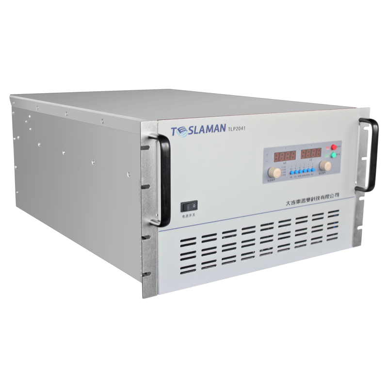
The supply cabinet is 600 mm wide, 800 mm deep, 1800 mm tall, with IP65 protection. The cabinet is made of 304 stainless steel, with a powder coat finish. The cabinet door has a silicone gasket, and the gasket is replaced annually. The cabinet cooling is by a heat exchanger, with ambient air on the outside and filtered internal air on the inside. The heat exchanger prevents salt-laden air from entering the cabinet. The heat exchanger filters are replaced quarterly.
The supply output is adjustable from 0 to 80 kV, with a current limit of 2 mA. The voltage is set by a front panel knob, and the setting is locked by a key switch. The technician selects the voltage based on the powder type and the workpiece geometry. Complex shapes with recessed areas use a lower voltage, 60 kV, to avoid back ionization. Flat plates use the full 80 kV, for maximum transfer efficiency.
The spray booth is a downdraft type, with a floor grate that draws air downward. The booth air flow is 3000 m3 per hour, and the overspray is captured by filters. The filters are polyester type, 0.5 μm rating, and are replaced when the differential pressure exceeds 0.1 kPa. The booth exhaust is filtered before discharge, to meet environmental regulations. The booth lighting is explosion-proof, 24 V, with sealed fixtures.
The workpiece grounding is critical for electrostatic spray. The workpiece hangs on a conveyor, and the conveyor contacts a grounding brush. The brush is carbon fiber, and the contact resistance is measured weekly. The resistance must stay below 1 Ω. The workpiece surface is blasted to Sa 2.5 grade, before spraying, to remove rust and mill scale. The blasted surface is sprayed within 4 hours, to prevent flash rust.
The supply safety interlock is a foot switch on the booth floor. The technician presses the foot switch to energize the gun, and releases the switch to de-energize. The foot switch is a dual-pedal type, with a hold position and a momentary position. The dual-pedal design prevents accidental energization, because the technician must press and hold the pedal. The foot switch is rated IP65, and the cable is shielded.
The maintenance log lists routine tasks. Each shift, the technician records the voltage setting and the film thickness. Weekly, the technician inspects the cable jacket and the grounding brush. Monthly, the insulation resistance is measured with a 2500 V megohmmeter. Quarterly, the divider is calibrated against a 0.1 percent standard. Annually, the cabinet gasket is replaced. The log is signed at each step, and the record is filed in the quality system.
The input side of the supply draws 230 V single phase at 5 A. A 3 kVA isolation transformer sits between the wall outlet and the supply, to isolate the booth ground from the plant ground. The isolation transformer has a 1500 V insulation rating between primary and secondary. The input cable is copper, 2.5 mm², rated for 16 A, routed along the booth wall. The input breaker is a 10 A miniature type, with a thermal-magnetic trip. The input power factor is 0.95, measured with a power analyzer during commissioning.
The high-voltage transformer inside the supply cabinet is oil insulated, with a 5 L oil volume. The oil temperature reaches 45 degrees after 8 hours of continuous operation at 80 kV and 2 mA, against an ambient of 25 degrees. The silica gel breather on the transformer tank changes color after 6 months, and the gel is replaced before the color reaches half saturation. The oil breakdown voltage is tested annually, and the last measurement showed 38 kV per 2.5 mm gap, well above the 25 kV replacement threshold. The transformer sound level is 48 dB at 1 m, measured with a sound level meter during commissioning.
The output divider is a series chain of 100 MΩ high-voltage glass glaze resistors, totaling 2 GΩ. The divider tap at 1:2000 feeds the control board ADC. The divider is calibrated quarterly against a 0.1 percent standard divider. The calibration drift over 12 months was 0.3 percent, equivalent to 240 V at 80 kV. The drift is within the 1 percent acceptance limit, but the divider is scheduled for resistor replacement at the 24 month mark.
The powder coating process parameters are written in the procedure manual. The powder is an epoxy type, with a particle size distribution of 30 to 50 μm. The powder is cured in an oven at 200 degrees for 10 minutes, after spraying. The cured film thickness is measured by a magnetic gauge, and the adhesion is tested by a cross-cut method. The film gloss is measured by a gloss meter, at 60 degrees incidence. The process parameters are optimized for each workpiece type, and the optimization is documented in the quality system.
The customer acceptance test was run over two days. Day one covered the flat plate spraying at 80 kV, measuring the film thickness uniformity and the transfer efficiency. Day two covered the complex shape spraying at 60 kV, measuring the recessed area coverage. The test report was signed by the customer representative, and the supply entered the 12 month warranty period.
The spray booth maintenance log lists routine tasks. Each shift, the technician records the booth airflow and the filter differential pressure. Weekly, the technician cleans the booth floor and the grate. Monthly, the booth lighting is inspected, and the fixtures are cleaned. Quarterly, the exhaust fan is inspected, and the fan blades are cleaned. Annually, the booth filters are replaced. The log is signed at each step, and the record is filed in the quality system. The booth once had a filter differential pressure alarm, and the filters were replaced within 2 hours.
The offshore environment presents additional challenges. The shipyard is located on the coast, with salt-laden air and high humidity. The supply cabinet is washed monthly with fresh water, and the exterior is inspected for corrosion. The stainless steel hardware is coated with anti-seize compound, to prevent galling. The cabinet door gasket is inspected quarterly, and replaced annually. The cable jacket is cleaned weekly, to remove salt residue. The supply has been in service for 18 months, and the cabinet exterior shows light surface rust at the screw holes, which is treated with corrosion inhibitor.
The corrosion coating process is qualified per ISO 12944, with the film thickness measured at 80 to 120 μm. The adhesion is tested by a pull-off method, with the adhesion strength exceeding 5 MPa. The coating is tested for salt spray resistance, with 1000 hours of exposure without rust. The test coupons are prepared alongside the production workpieces, and the coupons are tested after each batch. The test results are recorded in the quality system, and the batch is released only when all tests pass.
The supply control panel has a voltage display, a current display, a power switch, and an emergency stop button. The voltage display is a digital type, with 0.1 kV resolution. The current display is a digital type, with 0.01 mA resolution. The emergency stop button is a mushroom type, red, mounted on the front panel. The emergency stop circuit is hardwired, and the button cuts the high-voltage output within 20 ms. The panel is labeled with the supply model, the serial number, and the manufacturing date. The panel is locked by a key switch, to prevent unauthorized adjustment.
Conveyor hook grounding is a quiet failure point in a salt-laden shop. Powder that builds up on the hook contact surface cures into an insulating layer, and the measured hook-to-work resistance climbs from below 1 kΩ on a clean hook to 80 kΩ after three weeks without cleaning. Past 1 MΩ, the wrap-around on the far side of a pipe section drops from 75 percent to 40 percent, and a batch of 60 flanges went out with bare spots at the bolt holes. Hooks now go through a burn-off oven every 5 working shifts, and one hook per load is checked with a 100 V continuity meter; anything above 100 kΩ is replaced before the next batch. The 20-minute cycle runs in the evening shift, and contacts are filed afterward because oven oxide skin adds back a few kiloohms.
Powder reclaim is the first thing coastal humidity attacks. Overspray is pulled through a cyclone and sieved back into the hopper at a nominal 85 percent reclaim ratio, but above 70 percent booth humidity the powder agglomerates, the 120 μm return sieve blinds, and one July week the measured ratio fell to 61 percent with two sieve tears from forced brushing. A dehumidifier holding the booth at 55 to 60 percent brought the ratio back to 82 percent, still 3 points below the dry-season value because reclaimed powder carries more fines. The blend now runs at 30 percent reclaim to 70 percent virgin; above 40 percent, epoxy film gloss drops from 85 to 78 units and salt spray hours fall from 1000 toward 800. Sieve pressure drop and humidity are logged each morning, and a rise above 1.2 kPa triggers a sieve change.
The corona electrode needle wears by the meter, and the drift shows up in the output current rather than the voltage. A new needle is 0.8 mm diameter with a polished tip; after 40 spray hours the tip erodes to a 0.25 mm radius, the corona envelope widens, and the current at a fixed 80 kV drops from 1.9 mA to 1.5 mA. Edge film still reads 90 μm, but thickness scatter across a 3 m panel widens from plus or minus 8 μm to plus or minus 22 μm, and the rejection rate on gloss panels doubled in a traced month. Needles are now replaced at 35 hours or whenever the current at 80 kV reads below 1.7 mA, whichever comes first. The seat is wiped with an alcohol-free solvent first; a film of old grease once held a new needle 1 mm off axis and pulled the spray cone to one side.
Cold steel from the open yard will not hold a uniform coat. Pipe sections delivered from the blasting bay in winter sat at 4 degrees, and on reaching the booth at 22 degrees the first powder layer attracted moisture, gelled unevenly, and the cured film showed pinholes at 4 spots per square meter; sections preheated to 15 to 20 degrees in the gas-fired oven showed fewer than 0.3. A 10-minute warm-up is now written into the line card even in summer, because a rain-wetted plate and a dry plate can sit on the same conveyor and the gun operator cannot tell the difference by eye. Surface temperature is measured on every load; the extra 4 minutes of oven time per rack and an 8 percent higher gas bill are cheaper than reblast and reshoot on 2 tonnes of rejected pipe.
The supply has a serial communication port, RS 232, for remote monitoring. The port connects to the booth control system, and the supply status is displayed on the booth monitor. The communication cable is shielded, and the shield is grounded at the supply end. The communication protocol is Modbus RTU, with 9600 baud rate. The port is checked annually, and the communication error rate is logged in the maintenance record.
A batch of 40 valve bodies came back from the shipyard with the bore inner wall measuring only 45 μm against the 80 μm specification, while the outside flange measured a full 85 μm. The bore acts as a Faraday cage, and the charged powder particles cannot reach the inner wall at 80 kV because the field lines terminate on the flange rim. The first attempt at 60 kV worsened the coverage, because the lower charge on each particle weakened the field attraction even more. The fix combined three changes: the gun was fitted with a 15 mm extension nozzle that reaches 80 mm into the bore, the voltage was dropped to 55 kV, and the technician holds the gun inside the bore for 4 seconds per pass instead of sweeping at 0.5 m per second. The inner wall then measured 82 μm, at the cost of 30 seconds extra per valve body and a transfer efficiency that dropped from 78 percent to 64 percent. The overspray powder that used to land on the workpiece now loads the booth filters harder, and the filter replacement interval shortened from 3 months to 7 weeks. The extension nozzle wears a powder erosion groove after about 600 bodies, and the nozzle is swapped on a 500 body preventive schedule. The bore coverage is now checked on every 10th valve body with a magnetic gauge probe that fits inside the bore, and a reading below 70 μm stops the line until the gun angle is reworked.
The supply has run for 18 months. The high-voltage cable has been replaced twice. The spray gun electrode has been replaced three times, at 500 hour intervals. The cabinet gasket has been replaced once, at 12 months. The unresolved issue is the salt contamination on the cabinet exterior. The salt dust accumulates on the cabinet surface, and the corrosion starts at the screw holes. The cabinet is washed monthly with fresh water, and the screw holes are coated with corrosion inhibitor. A stainless steel upgrade is under evaluation, and the upgrade is scheduled for the next cabinet replacement.