








Adhesion Optimization of Electrostatic Flocking High-Voltage Power Supplies in Automotive Interiors and High-End Textiles
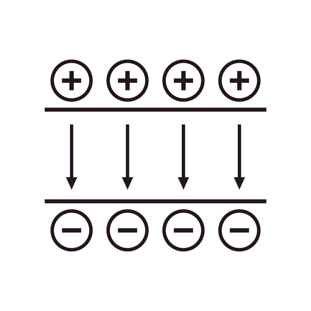
Flocking places short fibres upright on an adhesive-coated surface by accelerating them through an electric field, and the density and orientation of the fibres determine whether the finish feels like suede or like a scrubbing brush. The field is produced by a supply in the twenty to eighty kilovolt range acting between a grounded substrate and an electrode above it, and the supply's behaviour during the deposition window decides how many fibres arrive, how straight they stand and how many are lost.
Field strength at the substrate is the controlling variable, and it is not the same as the voltage at the supply. Electrode geometry, the distance to the substrate, the resistivity of the substrate and the humidity of the air all divide the applied voltage into a field. A supply that holds voltage constant while the humidity changes delivers a field that changes, and the resulting flock density varies between the first panel of the shift and the last.
Humidity is the dominant environmental variable in flocking. At forty percent relative humidity the surface of the adhesive layer conducts enough to relax charge, and fibres that land upright stay upright; at seventy percent the charge leaks away during the flight and fibres arrive at an angle. The supply cannot control the humidity, but a voltage that can be trimmed in real time, with feedback from a field probe, compensates for the change.
Fibre length and denier set the charge-to-mass ratio that the field must work against. Longer fibres carry more charge but also more mass, and the acceleration depends on the ratio; a supply that produces the right field for three-millimetre fibre will over-accelerate one-millimetre fibre and drive it flat against the surface. Multiple electrode zones with independent voltage control allow the same line to run different fibre lengths without changing the mechanics.
Adhesive viscosity and cure rate interact with the electrical process. A fibre arrives at the surface with residual charge, and the charge must dissipate before the adhesive cures or the fibre will lean as the field collapses. A supply that removes the voltage abruptly leaves a charge distribution on the surface that discharges unevenly, and the fibres nearest the electrode lean furthest. A controlled decay, lasting one to two seconds, lets the charge relax while the field still holds the fibres upright.
Electrode design and the supply's output impedance form a resonant circuit with the capacitance of the flocking chamber. A large chamber with several square metres of electrode area presents hundreds of picofarads, and a supply with a fast loop and a low output impedance will ring after a discharge event. Damping in the loop and a series resistance at the electrode convert the ring into a controlled decay, at the cost of a slower rise.
Discharge events in the chamber are frequent and are the main cause of visible defects. A clump of fibre or a conductive path through the adhesive produces a spark that leaves a bare patch, and the energy in the spark determines the size of the patch. Limiting the stored energy by keeping the output capacitance small and adding current limiting at the electrode keeps patches below the visible threshold.
The supply's current limit is a production parameter, not just a protection. During normal flocking the current drawn is small, and the current limit should sit just above it so that a developing fault is caught early. Setting the limit high to avoid nuisance trips allows a fault to persist and produces a large patch before the operator notices.
Automotive interior parts have complex geometry, and the field follows the geometry rather than the voltage. A concave surface sees a weaker field, and a convex edge sees a concentrated one; independent zones or a shaped electrode compensate. A single supply feeding all zones through one electrode produces uneven density that is visible on a curved part and impossible to correct by adjusting a single voltage.
Textile applications run continuously and value throughput, and the supply's rise time sets the cycle time. A supply that takes two seconds to reach full field limits the line to one part per few seconds; a supply that reaches full field in two hundred milliseconds allows a faster cycle but produces a larger spark if a fault occurs. The trade is resolved by using a fast rise with a current limit set low enough to bound the spark energy.
Cleanliness of the electrode affects the field more than the supply's regulation. Fibres accumulate on the electrode and change its effective shape, which changes the field distribution; the supply compensates by raising voltage, which increases the field at the closest points and produces local over-density. Cleaning the electrode on a schedule derived from the voltage trend, rather than from a calendar, keeps the distribution stable.
Measurement of the field, rather than of the voltage, is the only way to compare installations. A field probe at the substrate position, read at a fixed electrode voltage, gives a number that can be compared across lines. Two lines with the same supply voltage and different readings differ in geometry or humidity, and the correction belongs to the process rather than to the supply.
Safety design in flocking is dominated by the open chamber. The electrode is accessible during loading and unloading, and the supply must be interlocked so that the field is removed whenever the chamber is open. Residual charge on the electrode and on the part must be discharged through a bleeder before an operator can touch the work, and the bleeder's function should be verified rather than assumed.
Dust and fibre accumulation in the supply's cooling path is a slow failure mode. Flocking lines are dusty by nature, and a supply with forced air cooling will collect fibre in the heat sink within months, raising the internal temperature and drifting the voltage. Filtering the cooling air, or using a sealed supply with a heat pipe, avoids a failure that appears as unexplained density drift.
Cost of the flocking supply is modest relative to the line, so the decision should be made on features rather than on price. Independent zones, a controlled decay, a field probe input and a low current limit are the features that separate a production supply from a general-purpose unit, and each corresponds to a defect class that will otherwise appear in the finished part.
Limits of the supply's influence are clear. Adhesive chemistry, fibre quality and chamber humidity set the achievable density; the supply sets the field that the process uses. No supply can make a high-humidity chamber behave like a dry one, and attempting to compensate with higher voltage produces sparks instead of density.
An acceptance test that uses the process is the practical one. Flock a set of standard panels at three voltages and two humidity levels, measure density and orientation by image analysis, and record the voltage and field probe readings. The resulting map shows the operating window, and the window's width is the best measure of whether the supply and the process fit together.
Multiple stations on one line need matched supplies, not identical ones. Two stations with the same model but different electrode geometries produce different fields at the same voltage, and parts flocked at one station differ from parts flocked at the other. Setting each station's voltage against a field probe rather than against the nameplate value brings the two into alignment.
Fibre recovery systems and the supply interact through the air path. A recovery duct that pulls air across the electrode changes the field by removing charge carriers and by cooling the electrode; a supply tuned with the duct off will over-flock when the duct is running. Commissioning with the ventilation in its production configuration avoids a recurring mismatch between trial and production.
Records of voltage, humidity and field probe readings per shift make density complaints tractable. When a batch is rejected, the records show whether the humidity moved outside the window or the voltage was trimmed, and the correction is a process change rather than a supply change. Without the records, every complaint begins with a guess.
Spares strategy should match the failure pattern. Electrodes and current-limiting resistors fail first, the supply's power stage fails rarely, and the control board fails somewhere between. Holding one electrode set and one current-limiting module for each station covers most outages, and the cost is small compared with a stopped line.
Limits of the electrical approach should be stated. A substrate with an uneven adhesive coat produces uneven density regardless of the field, and a fibre batch with inconsistent length produces inconsistent orientation regardless of the voltage. The supply controls the field, and the field is one of several variables that must all be in range for the finish to be acceptable.
A final practical note on commissioning: bring the field probe into the routine. Reading the field at a fixed reference point once per shift, and comparing with the value recorded when the process was validated, turns a subjective judgement about finish quality into a measurement. When the reading moves, the cause is either the electrode, the humidity or the supply, and the order of checking follows from the reading's magnitude.