Electromagnetic Pulse Protection for High-Voltage Power Supplies in Lithography Machines
The stability of high-voltage power supplies (requiring stable DC outputs of kilovolts to tens of kilovolts) in advanced lithography machines directly determines exposure accuracy. However, transient electromagnetic pulse (EMP) interference (with rise times as short as nanoseconds and field strengths up to kV/m) can invade systems through radiation coupling or power conduction paths, causing arc discharge, component breakdown, or control signal disruption, leading to batch scrapping of wafers. To address this challenge, a comprehensive protection system integrating multi-stage circuits, spatial shielding, and active suppression technologies is essential.
1. EMP Threats to High-Voltage Power Supplies
• Broad Spectrum Coverage: Nuclear EMP (NEMP) spans DC to hundreds of MHz, while non-nuclear EMP (e.g., HPM weapons) reaches GHz, easily overlapping with power supply bands and inducing resonance.
• High Energy Density: Instantaneous power up to MW-level couples kA-level surge currents through cables, exceeding the tolerance limits of TVS and other devices.
• Lithography-Specific Sensitivity: Feedback control circuits (e.g., DC-DC converters) are vulnerable to microsecond-level voltage fluctuations. EMP can disrupt PWM signals, destabilizing constant-current output.
2. Core Protection Technologies
(1) Multi-Stage Circuit Architecture
For conductive paths, a three-stage energy gradient dissipation design is adopted:
• Primary Dissipation: Metal-oxide varistors (MOVs) with ≥20kA current capacity, in series with gas discharge tubes, dissipate >90% of surge energy, clamping residual voltage below 1kV.
• Secondary Clamping: TVS diodes (response time <1ns) paired with 5μH air-core decoupling inductors elevate MOV voltage via Ua = Ub + L·di/dt, forcing early activation and reducing residual voltage below 300V.
• Tertiary Filtering: π-filters (common-mode chokes + differential capacitors) suppress residual noise above 100MHz, achieving >40dB insertion loss.
(2) Enhanced Spatial Shielding
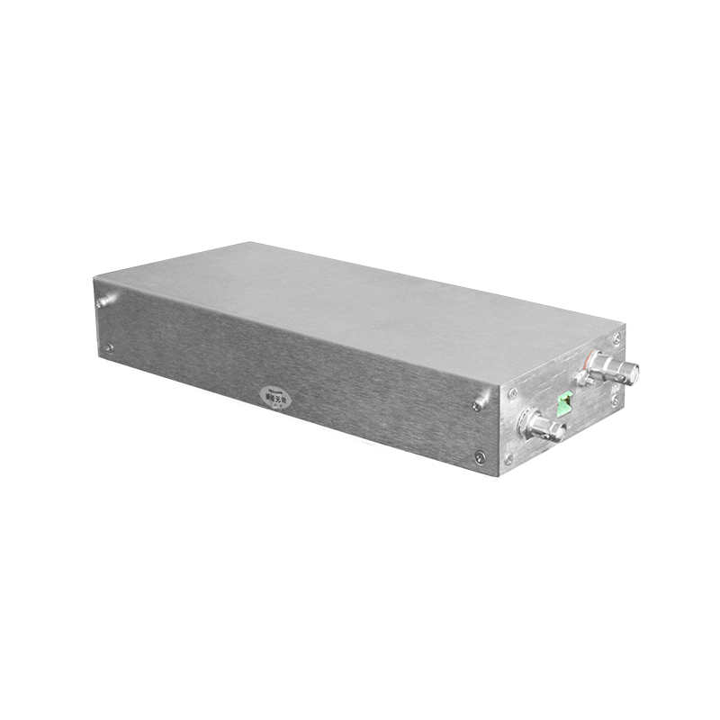
• Composite Enclosure: Power modules should be housed in dual-layer structures:
• Outer layer: Glass fiber skin + aluminum mesh (thickness ≥2mm) with textured surfaces to scatter EM waves.
• Inner layer: Glass fiber honeycomb cores (hexagonal cells filled with glass beads) dissipate energy via eddy currents.
• Active Plasma Protection: Carbon fiber electrodes in the interlayer release low-temperature plasma when EMP intensity exceeds thresholds, enabling μs-level dynamic absorption.
(3) Grounding and Isolation Optimization
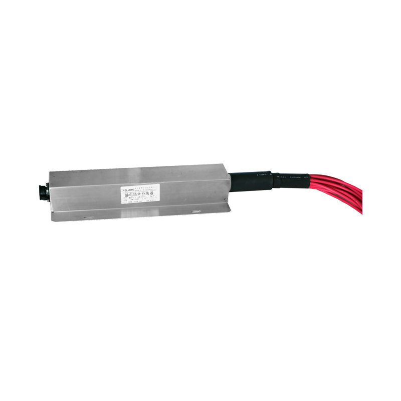
• Low-Impedance Grounding: Copper strips directly connected to enclosures (impedance <0.1Ω) prevent potential elevation.
• Fiber-Optic Isolation: Critical signals (e.g., exposure triggers) use optical fibers to block ground-loop coupling.
3. Simulation-Driven Design and Validation
• Co-Simulation: CST/SPICE models predict cable coupling (e.g., ≥5kV induced in 1m cable under 10kA/m EMP), optimizing component parameters.
• Testing: Injecting 6kV pulses with 2ns rise time, post-protection residual voltage must be <120V (meeting IEC 61000-4-5 Level 4).
4. Conclusion: The Value of Integrated Protection
EMP protection for lithography power supplies requires balancing speed (ns response), energy (kA dissipation), and space (mm-scale shielding). Future trends include adaptive systems—e.g., FPGA-dynamic decoupling inductors for varying EMP spectra. Only by unifying conductive protection and spatial shielding can high-voltage supplies achieve sub-microsecond stability under extreme EM conditions, enabling zero-defect power for chip manufacturing.