Linear High-Voltage Power Supply Linearity Optimization Measures
2.1 Application Background and Technical Difficulties
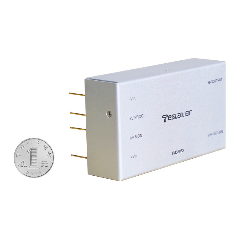
Linear high-voltage power supplies are critical in precision measurement fields such as mass spectrometry, electron microscopy, and semiconductor wafer testing, where linearity (output voltage deviation from ideal linear curve) directly affects measurement accuracy. When the output voltage exceeds 10kV, factors such as amplifier non-linearity, reference voltage drift, and load effect easily cause linearity errors to exceed ±0.1%, failing to meet the requirements of high-precision equipment.
2.2 Core Optimization Measures
2.2.1 Reference Voltage Source Optimization
Adopt a low-temperature-drift bandgap reference (such as the AD588) with a temperature coefficient of ≤1ppm/℃, and add a platinum resistance (PT100) temperature compensation circuit. The PT100 real-time detects the ambient temperature (measurement accuracy ±0.1℃) and feeds back to the operational amplifier, adjusting the reference voltage by ±5mV within the temperature range of -20℃ to 60℃ to offset the temperature drift of the reference source.
2.2.2 Amplifier Circuit Improvement
Use a cascode amplifier structure (common-emitter + common-base combination) instead of a single common-emitter amplifier. The common-base stage reduces the input capacitance of the common-emitter stage by 1/β (β is the current gain of the transistor), suppressing the phase shift caused by the Miller effect and reducing non-linear distortion. At the same time, a polypropylene capacitor (temperature coefficient ≤50ppm/℃) is used as the compensation capacitor, which maintains stable capacitance within the operating temperature range and avoids linearity degradation caused by capacitance drift.
2.2.3 Load Effect Suppression
Add an emitter follower as a buffer stage between the amplifier output and the load. The emitter follower has a low output impedance (≤10Ω) and a high input impedance (≥1MΩ), which reduces the impact of load impedance changes (such as load resistance varying from 1kΩ to 10kΩ) on the output voltage. In addition, shielded twisted-pair cables are used for high-voltage output wiring, and a single-point grounding design is adopted (ground resistance ≤1Ω) to suppress electromagnetic interference (EMI) and avoid linearity errors caused by EMI.
2.3 Application Verification
In the test of a 15kV linear high-voltage power supply, the linearity error was measured using a high-precision digital multimeter (Keithley 2002) at output voltages of 3kV, 6kV, 9kV, 12kV, and 15kV. The linearity error after optimization was ≤±0.05%, which was 50% lower than before optimization, fully meeting the linearity requirements of high-precision electron microscopes.