Integration of High Voltage Power Supply in Microfluidic Chip Electrokinetic Sample Injection System
Microfluidic chip technology has revolutionized analytical chemistry and biochemistry by enabling complex laboratory operations to be performed on miniature chip devices. Electrokinetic sample injection is a fundamental operation in microfluidic systems, using electric fields to manipulate and inject sample plugs into separation channels for analysis. The high voltage power supply that drives the electrokinetic injection must provide precise control of voltage and timing while being integrated into the compact microfluidic instrument. The integration of high voltage power supplies into microfluidic systems presents unique challenges related to miniaturization, precision, and multi-channel coordination.
The electrical requirements for microfluidic electrokinetic injection depend on the chip design, channel dimensions, and buffer composition. Typical injection voltages range from hundreds to thousands of volts, with currents from nanoamps to microamps depending on the channel geometry and buffer conductivity. The power supply must provide extremely precise voltage control because the injection volume depends directly on the electric field strength and duration. The load presented by the microfluidic chip varies with buffer composition, temperature, and channel condition, requiring the power supply to adapt to these variations while maintaining injection precision.
Electrokinetic injection principles rely on electroosmotic flow and electrophoretic migration. When a voltage is applied across a microfluidic channel filled with buffer solution, the electric field drives fluid flow through electroosmosis and solute migration through electrophoresis. The combination of these effects determines the injection plug volume and composition. The power supply must generate the appropriate electric field to achieve the desired injection characteristics. The injection precision depends on the stability and accuracy of the applied voltage and timing.
Cross-injection and pinched injection are common injection schemes in microfluidic systems. Cross-injection uses a simple intersection of sample and separation channels with voltage switching to control injection. Pinched injection uses additional focusing voltages to define the sample plug boundaries more precisely. Each injection scheme has specific requirements for voltage levels, switching timing, and channel coordination. The power supply must support the specific injection scheme used in the microfluidic chip. Multiple independently controlled voltage channels are typically required.
Multi-channel voltage control is essential for complex microfluidic operations. Modern microfluidic chips may have multiple injection points, separation channels, and detection zones that require independent voltage control. The power supply must provide multiple output channels with independent voltage adjustment. Channel-to-channel isolation must be maintained to prevent crosstalk between adjacent channels. The number of channels and the isolation requirements depend on the chip design and application complexity.
Voltage switching speed and timing accuracy determine injection precision. The injection process involves rapidly switching voltages between injection mode and separation mode. The switching must be fast enough to define sharp injection plug boundaries. The timing accuracy must be sufficient to achieve reproducible injection volumes. The power supply must switch between voltage levels with minimal overshoot and settling time. Advanced injection schemes may require complex voltage switching sequences with precise timing.
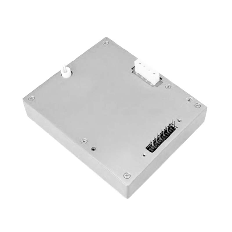
Miniaturization of the high voltage power supply is critical for portable microfluidic instruments. Laboratory-based microfluidic systems can use benchtop power supplies, but point-of-care and field applications require compact integrated solutions. Miniaturization of high voltage circuits is challenging due to insulation requirements and voltage clearance distances. The power supply must be designed to fit within the instrument enclosure while meeting all electrical safety requirements. Advances in high voltage integrated circuits and packaging technology enable further miniaturization.
Low current operation presents measurement and control challenges. The currents in microfluidic channels are typically in the nanoampere to microampere range, making accurate current measurement difficult. Current monitoring is important for detecting channel blockages, buffer depletion, and other problems. The power supply must incorporate sensitive current measurement with adequate noise performance. The measurement circuit must not introduce significant leakage current that could affect the electrokinetic processes.
Buffer composition and conductivity affect the power supply requirements. Different buffer solutions have different ionic strengths and conductivities that affect the electrokinetic behavior. Higher conductivity buffers require higher currents for the same electric field strength. The buffer composition can change during operation due to electrochemical reactions at the electrodes. The power supply must accommodate the range of buffer compositions used in the specific application. The power supply design must consider the electrochemical compatibility with the buffer system.
Electrode integration affects the power supply design and performance. The electrodes in contact with the buffer solution are critical components that affect the electrokinetic processes. Platinum electrodes are commonly used due to their chemical stability and electrochemical properties. The electrode design affects the electric field distribution in the channels and the generation of electrochemical byproducts. The power supply must drive the electrodes with appropriate voltage while managing the electrochemical reactions. Electrode degradation over time can affect the injection performance.
Temperature effects on electrokinetic injection must be managed. Joule heating from the applied electric field can increase the buffer temperature, changing the viscosity, conductivity, and electroosmotic mobility. Temperature variations can cause injection volume variability and separation performance degradation. The power supply must be coordinated with temperature control systems to maintain stable operating conditions. The power level must be managed to minimize Joule heating while achieving the required injection performance.
Safety considerations are important even at the relatively low power levels used in microfluidic systems. The high voltage can still pose a shock hazard, particularly in wet laboratory environments. The power supply must incorporate current limiting and fault detection to protect operators. The microfluidic chip and electrodes must be properly insulated to prevent accidental contact. The safety design must comply with applicable laboratory equipment standards. Safety interlocks may be required for automated instruments.
Integration with detection systems enables complete analytical capability. The microfluidic chip typically includes optical or electrochemical detection downstream of the injection point. The power supply must not generate interference that could affect the detection sensitivity. The power supply switching transients must be managed to avoid disturbing the detection electronics. The timing between injection and detection must be coordinated for optimal analytical performance. The integration design must consider the complete analytical workflow.
Automation and control software enable reproducible microfluidic analysis. The power supply must interface with instrument control software that manages the injection sequence, separation conditions, and data acquisition. The software must provide flexible control of voltage parameters and timing for different analytical methods. Automated calibration and quality control procedures improve analytical reliability. The software interface must be intuitive for laboratory users while providing access to advanced control parameters for method development.