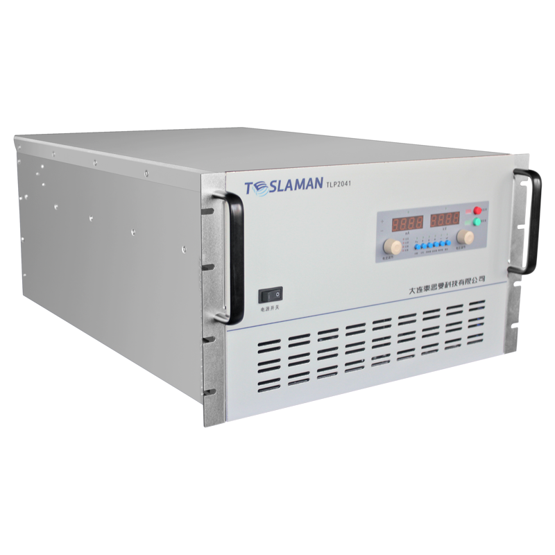
Loss Analysis and Optimization Design of Magnetic Components in High Frequency High Voltage Power Supply
High frequency operation enables size and weight reduction in high voltage power supplies by allowing smaller magnetic components and filter capacitors. However, higher frequencies increase the losses in magnetic components including transformers and inductors, creating thermal challenges and potentially limiting the efficiency gains. Loss analysis and optimization of magnetic components enables high frequency designs that achieve both small size and good efficiency.
Magnetic components in high voltage power supplies include the main power transformer that provides voltage step up and isolation, filter inductors that smooth the output current, and sometimes coupled inductors for multi output supplies. These components store and transfer energy through magnetic fields in their cores and windings. The losses in these components convert electrical energy to heat, reducing efficiency and requiring thermal management.
Core losses in magnetic materials arise from hysteresis and eddy currents. Hysteresis loss occurs because the magnetization of the core material lags the applied magnetic field, with energy dissipated in each magnetization cycle. The hysteresis loss per cycle is approximately constant for a given flux swing, so the total hysteresis loss scales linearly with frequency. Eddy current loss occurs when the changing magnetic field induces circulating currents in the core material, with the loss proportional to the square of frequency and the square of flux density.
Core material selection for high frequency operation requires materials with low loss at the operating frequency. Ferrite materials have high resistivity that minimizes eddy currents, making them suitable for frequencies from tens of kilohertz to megahertz. The specific ferrite grade is selected based on the frequency and flux density requirements, with different grades optimized for different frequency ranges. Nanocrystalline and amorphous materials offer lower loss than ferrites at lower frequencies but may not be suitable for very high frequency operation.
Winding losses arise from the resistance of the conductor to the current flow. At low frequencies, the loss is simply the product of resistance and current squared, with the resistance determined by the conductor length, cross section, and material resistivity. At high frequencies, skin effect causes the current to concentrate near the conductor surface, increasing the effective resistance. Proximity effect, where currents in adjacent conductors influence the current distribution, further increases the loss in multi layer windings.
Litz wire addresses skin and proximity effects by using multiple thin strands insulated from each other and transposed so each strand occupies all positions in the bundle. The strand diameter is chosen to be less than twice the skin depth at the operating frequency, ensuring uniform current distribution across the strand cross section. Litz wire reduces the AC resistance but has lower fill factor than solid wire, requiring larger core windows for the same number of turns.
Winding configuration optimization considers the placement of primary and secondary windings to minimize leakage inductance and proximity effects. Interleaving primary and secondary layers reduces the magnetic field between windings, reducing proximity effect losses and leakage inductance. However, interleaving complicates the winding process and may reduce the isolation between primary and secondary. The optimal configuration balances loss reduction against manufacturability and isolation requirements.
Thermal design of magnetic components ensures that the core and windings operate within their temperature ratings. The losses generate heat that must be transferred to the environment through conduction, convection, and radiation. The thermal resistance from the hot spot to the ambient determines the temperature rise for a given loss. Thermal modeling using finite element or analytical methods predicts the temperature distribution and guides the design.
Size optimization trades off core losses against winding losses to minimize the total loss or total size for a given application. Larger cores have lower flux density and lower core loss but require more winding material. Smaller cores have higher flux density and higher core loss but require less winding material. The optimal core size depends on the frequency, the power level, and the relative costs of core loss and winding loss. Design optimization tools automate the search for optimal parameters.
Measurement of magnetic component losses validates the design predictions. Calorimetric methods measure the total loss by the temperature rise of a known thermal mass. Electrical methods measure the input and output power, with the difference being the component loss. Loss separation techniques using different test frequencies or flux densities can distinguish core loss from winding loss. The measurements verify the loss models and identify any discrepancies that require design revision.