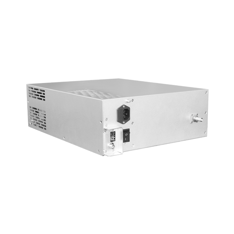
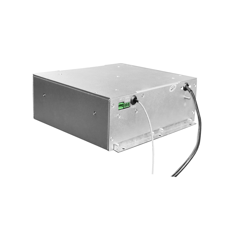
160kV High Voltage Power Supply Safety Protection Mechanism in Electron Beam System
Electron beam systems operating at 160 kilovolts require comprehensive safety protection mechanisms to prevent electrical hazards, equipment damage, and unintended X-ray exposure. The high voltage power supply serving as the energy source for electron beam generation must incorporate multiple layers of protection spanning electrical safety, interlock systems, fault detection, and emergency response. These protection mechanisms must function reliably under all operating conditions while avoiding nuisance trips that could interfere with normal operations, ensuring both personnel safety and operational productivity.
Personnel protection from electrical hazards represents the primary safety objective for high voltage systems. Direct contact with conductors at 160 kV causes immediate electrocution through both contact current and arc flash hazards. The power supply must be enclosed within grounded barriers that prevent access during operation. Interlocked doors and access panels interrupt power when opened, ensuring that high voltage is disconnected before personnel can enter the enclosure. The design must account for stored energy in capacitors and other components, which can remain hazardous for extended periods after power is removed. Grounding sticks or automatic discharge systems must dissipate stored energy before personnel access. The discharge time must be verified to ensure safe access within practical time constraints.
X-ray generation occurs whenever electrons accelerate through high voltage and strike a target. In electron beam systems, X-rays are generated intentionally at the workpiece but also unintentionally wherever electrons strike metal surfaces such as beam line components or chamber walls. Shielding must attenuate these X-rays to safe levels outside the equipment enclosure. The 160 kV operating voltage produces X-rays with maximum energy of 160 kiloelectron volts, requiring lead or steel shielding of calculated thickness based on expected X-ray intensity and regulatory exposure limits. Interlocks preventing X-ray generation when shielding is removed or compromised protect personnel from inadvertent exposure. Shielding verification measurements confirm adequate protection under actual operating conditions.
The electrical protection system must detect and respond to fault conditions within milliseconds to prevent equipment damage and arc propagation. Overcurrent detection responds to the rapid current increase characteristic of internal arc events. Current transformers or Hall-effect sensors monitor output current, with protection circuits initiating shutdown when thresholds are exceeded. The response time must be fast enough to limit energy delivered during the fault, preventing extensive damage to components. Electronic protection can respond within microseconds, significantly faster than electromechanical protection devices. The protection threshold settings must be optimized for different operating conditions and load characteristics.
Overvoltage protection prevents the output voltage from exceeding safe limits for the load and insulation systems. Voltage dividers or capacitive dividers monitor output voltage with accuracy sufficient for protection purposes. Separate voltage limit circuits provide redundancy for the main voltage regulation feedback. The protection system must respond to both steady-state overvoltage conditions and transient overvoltages that could occur during load faults or control system malfunctions. Spark gaps or surge arresters provide backup protection by clamping voltage to safe levels even if the electronic protection fails to respond. The protection circuit design must account for voltage measurement delays and response times.
Ground fault detection monitors for leakage currents that could indicate insulation degradation or personnel contact with high voltage. Differential current measurement compares the current leaving the power supply with the current returning, detecting any current flowing to ground. Ground fault protection is particularly important in electron beam systems where the workpiece may be grounded or connected to various potentials for beam deflection or material processing. The protection system must distinguish normal leakage current from fault conditions while maintaining sensitivity to genuine hazards. Ground fault monitoring also provides diagnostic information about insulation condition.
Thermal protection prevents damage from overheating of components with limited cooling capability. Temperature sensors monitor critical components including power semiconductors, transformers, and output stages. Multiple temperature sensors at different locations provide comprehensive monitoring, as hot spots can occur in locations distant from the primary cooling path. The protection system reduces power or initiates shutdown when temperatures exceed safe limits, with thermal time constants appropriate to the thermal capacity of the protected components. Temperature monitoring data supports predictive maintenance by identifying thermal trends.
Interlock systems integrate multiple protection functions into coherent safety systems. Safety interlocks prevent operation when equipment is in unsafe conditions, such as when covers are removed, cooling is inadequate, or vacuum levels are insufficient. Control interlocks prevent operation when process conditions are improper, such as incorrect beam parameters or absent workpieces. The interlock system must be designed to fail-safe, meaning that loss of signal, broken wires, or power failures result in safe shutdown rather than continued operation. Redundancy in critical interlock functions provides protection against single failures compromising safety. Interlock testing procedures verify correct operation of all safety functions.
Emergency stop systems provide immediate shutdown capability from multiple locations around the equipment. Emergency stop buttons must be prominently marked and readily accessible. Activating an emergency stop must remove all sources of hazardous energy, including electrical power, vacuum, and pressurized systems. The emergency stop function must be designed so that equipment cannot restart automatically when the stop condition is cleared, requiring deliberate operator action to resume operation. This prevents unexpected startup that could injure personnel who have entered the equipment area. Emergency stop circuits must be designed according to applicable safety standards.
Control system integrity affects overall safety system reliability. Programmable controllers managing interlocks and protection functions must be designed and programmed according to appropriate safety standards. Safety-rated controllers and redundant architectures provide the reliability required for critical protection functions. Software must be developed using quality processes that minimize the probability of errors affecting safety functions. Watchdog timers and self-checking routines verify that the control system is operating correctly, initiating safe shutdown if malfunctions are detected. Software verification testing must cover all safety-critical functions.
Documentation and training support safe operation of high voltage electron beam systems. Operating procedures specify normal operating sequences and response to abnormal conditions. Maintenance procedures address safe access to high voltage areas, including lockout-tagout procedures to prevent inadvertent energization while personnel are working inside equipment enclosures. Training ensures that operators and maintenance personnel understand the hazards involved and know how to work safely. Warning signs and labels identify hazardous areas and the nature of hazards present. Safety training must be documented and renewed periodically to maintain competency.