Low-Power Design of Channel Electron Multiplier High-Voltage Supply in Portable Mass Spectrometry and Environmental Monitoring
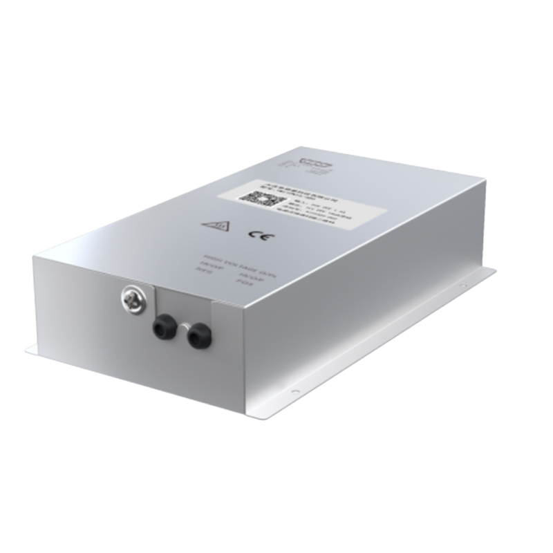
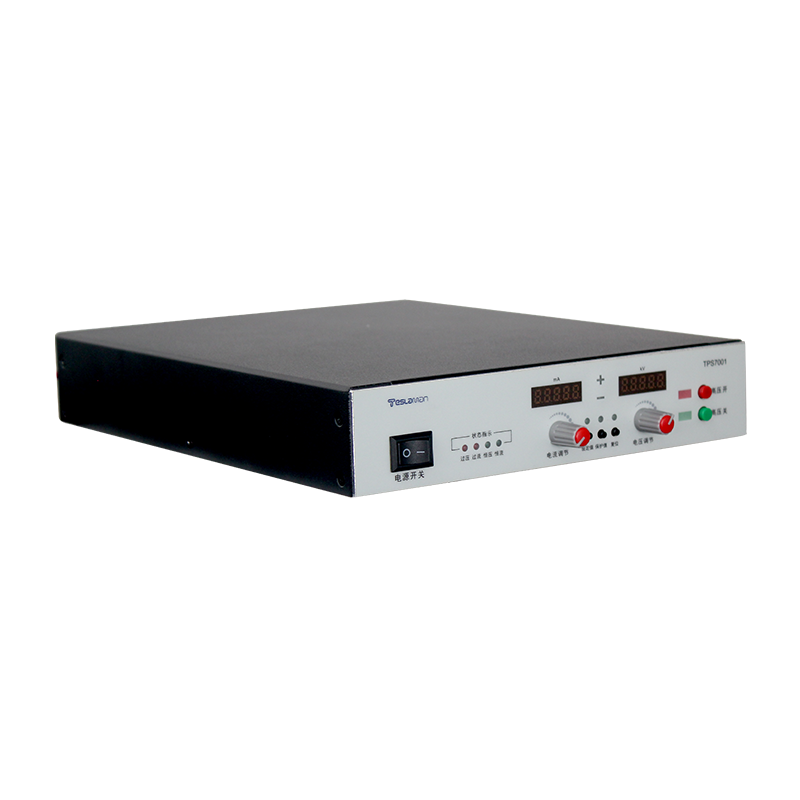
Portable mass spectrometers place tight limits on the power budget of the channel electron multiplier supply. The multiplier stage needs a stable high voltage across the dynode chain, yet the whole instrument runs from batteries in field conditions. The design target is a supply that delivers the required voltage with minimal power draw, low heat output, and stable behavior over a wide temperature range.
The multiplier gain is set by the voltage across the detector, and the voltage stability translates directly into the gain stability. A drift of a few hundred parts per million shifts the detection threshold and degrades the quantitative result. The reference element and the divider network are selected for low drift, and the divider is sealed against humidity because surface leakage shifts the ratio over time.
Power consumption is dominated by the conversion losses and the bleed current of the divider. The bleed current must supply the detector current and keep the divider linear, but an oversized bleed current wastes battery energy. The bleed value is sized from the maximum detector current and the required linearity, and the conversion stage operates at high efficiency across the load range.
Switching frequency is chosen to balance converter size and efficiency. A higher frequency shrinks the magnetic components but raises the switching loss, so the optimum sits near the point where the two loss terms are equal. The operating point is verified with a thermal survey of the converter at the rated output.
Field use exposes the supply to temperature swings, vibration, and condensation. The voltage reference is the most temperature-sensitive element, and the compensation channel corrects the output from the measured internal temperature. The compensation curve is generated during calibration and stored with the instrument.
The output filter must keep the ripple low without slowing the response. A low-ripple requirement forces a larger filter capacitance, while a fast recovery requirement forces a smaller value, and the compromise is documented in the specification. The measured ripple is recorded at the acceptance test and compared at each annual calibration.
Protection functions are simplified for the portable environment. Overload protection limits the output current, and an arc detection circuit shuts the output down when the detector develops a discharge. The recovery sequence is automatic, and the restart count is logged to reveal the detector condition.
Field calibration checks the voltage accuracy against a calibrated reference. The check interval is set by the drift history, and the records are kept with the instrument. A drift beyond the tolerance triggers a detailed inspection of the divider and the reference circuit.
Commissioning of the supply starts with a visual inspection of the high-voltage section and the cooling path, followed by a no-load voltage check and a load test at the rated output. The acceptance data are recorded against the specification table, and any deviation is resolved before the equipment enters service. The commissioning report becomes the baseline for all later comparisons.
Acceptance testing covers the electrical performance, the protective functions, and the mechanical integrity. The test sequence is defined in the procurement document, and each test has a pass criterion. The signed acceptance record accompanies the equipment through the service life and supports the warranty claims when a defect appears.
Preventive maintenance scheduling follows the operating hours recorded by the supply itself. The maintenance tasks are grouped by interval, and the short-interval tasks are performed during the regular downtime windows. The long-interval tasks are planned into the annual shutdown. The maintenance history is kept with the equipment and reviewed when the interval policy is updated.
Calibration management covers the measurement channels used by the supply and the instruments used to verify the supply. Each channel has a calibration interval and a tolerance, and the calibration records are traceable to the laboratory standards. The calibration status is checked before a critical measurement campaign starts.
Documentation control ensures that the drawings, the manuals, and the configuration records reflect the installed equipment. Any modification is documented with the change reason and the verification result. The document set is reviewed at planned intervals, and the obsolete versions are archived rather than discarded.
Spare parts management matches the stock level to the failure statistics of the equipment family. The fast-moving parts are kept on site, and the slow-moving parts are sourced on demand. The stock review is performed quarterly, and the review data include the part cost and the delivery lead time.
Safety procedures around the high-voltage equipment are written, reviewed, and rehearsed. The procedures cover the access control, the discharge sequence, and the use of personal protective equipment. The rehearsal results are recorded, and the procedure is revised when the rehearsal reveals a gap.
Environmental control in the equipment room stabilizes the operating conditions of the supply. The temperature and the humidity are monitored continuously, and the alarm thresholds are set to protect the insulation and the electronics. The environmental records are kept alongside the equipment log for the correlation analysis.
Data analysis turns the logged operating data into maintenance decisions. The voltage, current, temperature, and alarm trends are reviewed at planned intervals, and the deviations from the baseline trigger an investigation. The analysis report is shared with the engineering team and the maintenance crew.
Reliability assessment uses the field data collected from the equipment population. The failure rate, the repair time, and the availability are computed over a rolling period, and the results are compared with the design targets. The assessment output feeds the capital replacement plan and the spares strategy.
Energy efficiency of the supply affects the operating cost and the cooling load. The efficiency is measured at the representative operating points, and the improvement opportunities are evaluated against the implementation cost. The efficiency records are maintained for the lifetime comparison.
Training programs for the operating and maintenance staff are scheduled at defined intervals. The training covers the safe operation, the routine checks, and the fault diagnosis flow. The training effectiveness is verified with a written test and a practical exercise, and the results are filed with the personnel records.
Process qualification is performed whenever the equipment or the process recipe changes. The qualification plan defines the test articles, the acceptance criteria, and the data to be recorded. The qualification report is approved before the new condition enters production.