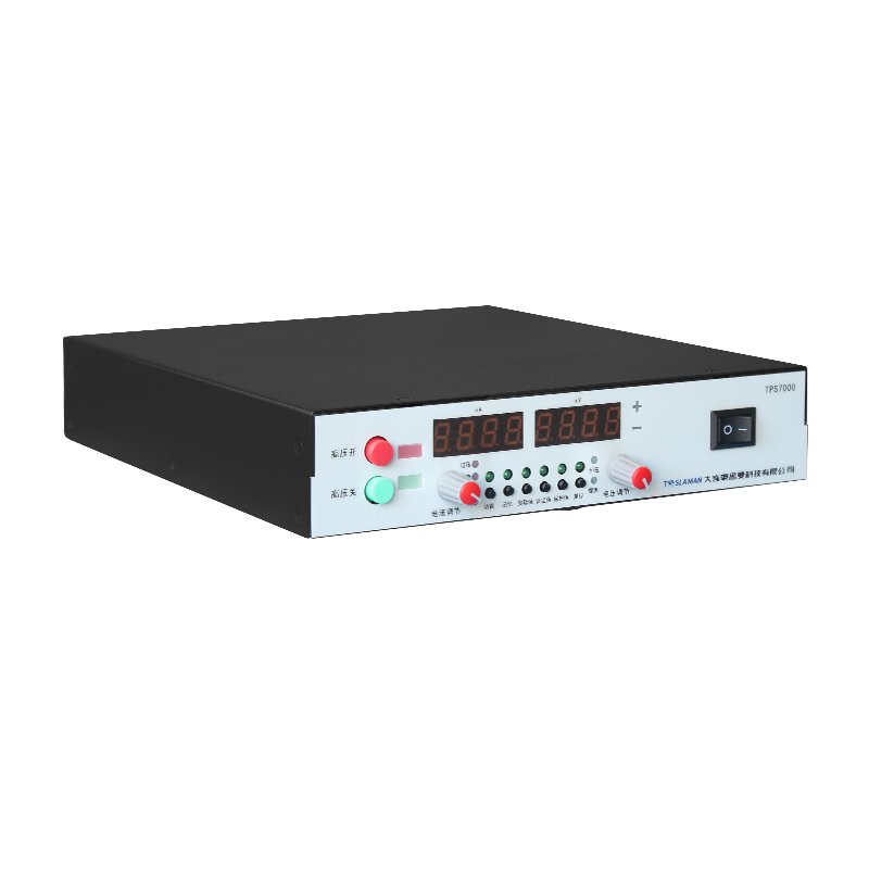
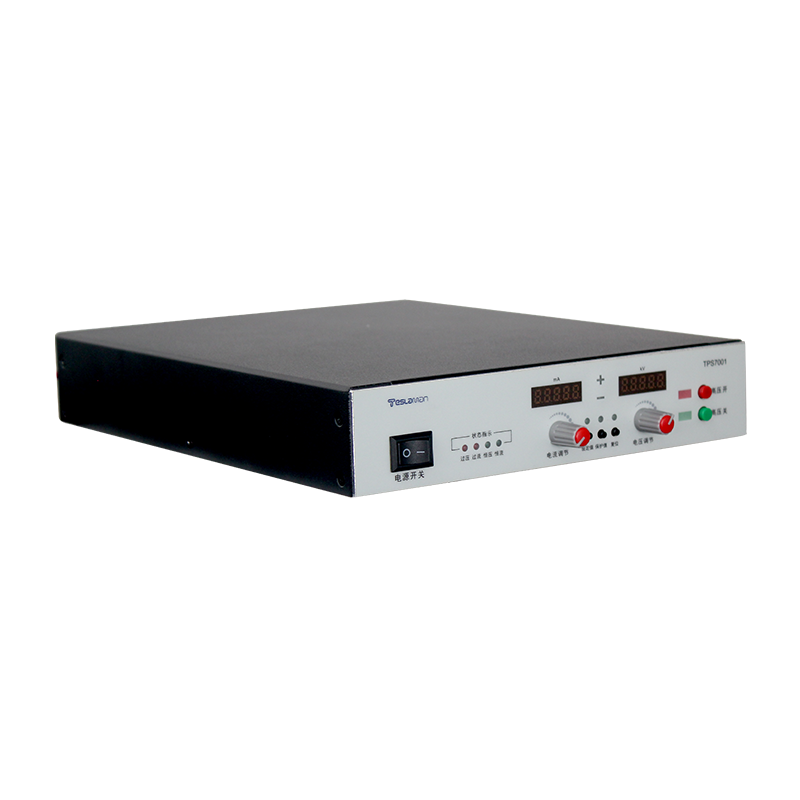
High-Voltage Control of Ion Implantation High-Voltage Supply in Solar Cell and GaN Device Doping
Ion implantation supplies for solar cell and GaN device doping must deliver a stable acceleration voltage and a controlled beam current. The doping depth is set by the acceleration voltage, and the doping dose is set by the beam current and the scan time. Both parameters are controlled by the high-voltage supply in cooperation with the beam line.
The acceleration voltage accuracy determines the depth uniformity across the wafer. A voltage error shifts the projected range of the implanted ions, and the shift is unacceptable for shallow junction devices. The reference and divider network set the accuracy, and the divider is calibrated against a traceable standard.
Beam current stability controls the dose uniformity. The current is measured at the high-voltage end, and the measurement value feeds the dose integration. The current measurement must be accurate over the operating range, and the measurement chain is calibrated with a standard current source.
Scanning adds a dynamic load to the supply. The beam current changes as the scan moves across the wafer, and the supply must hold the voltage while the load changes. The loop bandwidth is set from the scan frequency, and the voltage trajectory is verified during the acceptance test.
High-energy implantation demands a high acceleration voltage, and the insulation design must support the voltage continuously. The high-voltage section uses a sealed structure with controlled electric field distribution, and the partial discharge test is part of the acceptance procedure.
Temperature affects the voltage accuracy through the reference and the divider. The supply includes a temperature compensation channel, and the compensation curve is generated during calibration. The temperature of the critical components is monitored during operation.
Arc events in the beam line create a sudden load change. The supply detects the current transient and shuts down, and the recovery sequence restores the operating point after the beam line condition returns to normal. The arc statistics are recorded for the beam line diagnostics.
Process repeatability across lots requires that the supply performance remains stable over months of operation. The drift is compensated by the periodic calibration, and the calibration records show the drift history. A rising drift trend triggers an inspection of the aging components.
Spare parts management matches the stock level to the failure statistics of the equipment family. The fast-moving parts are kept on site, and the slow-moving parts are sourced on demand. The stock review is performed quarterly, and the review data include the part cost and the delivery lead time.
Safety procedures around the high-voltage equipment are written, reviewed, and rehearsed. The procedures cover the access control, the discharge sequence, and the use of personal protective equipment. The rehearsal results are recorded, and the procedure is revised when the rehearsal reveals a gap.
Environmental control in the equipment room stabilizes the operating conditions of the supply. The temperature and the humidity are monitored continuously, and the alarm thresholds are set to protect the insulation and the electronics. The environmental records are kept alongside the equipment log for the correlation analysis.
Data analysis turns the logged operating data into maintenance decisions. The voltage, current, temperature, and alarm trends are reviewed at planned intervals, and the deviations from the baseline trigger an investigation. The analysis report is shared with the engineering team and the maintenance crew.
Reliability assessment uses the field data collected from the equipment population. The failure rate, the repair time, and the availability are computed over a rolling period, and the results are compared with the design targets. The assessment output feeds the capital replacement plan and the spares strategy.
Energy efficiency of the supply affects the operating cost and the cooling load. The efficiency is measured at the representative operating points, and the improvement opportunities are evaluated against the implementation cost. The efficiency records are maintained for the lifetime comparison.
Training programs for the operating and maintenance staff are scheduled at defined intervals. The training covers the safe operation, the routine checks, and the fault diagnosis flow. The training effectiveness is verified with a written test and a practical exercise, and the results are filed with the personnel records.
Process qualification is performed whenever the equipment or the process recipe changes. The qualification plan defines the test articles, the acceptance criteria, and the data to be recorded. The qualification report is approved before the new condition enters production.
Failure analysis follows a defined path from the symptom to the root cause. The analysis uses the logged data, the physical evidence, and the repair records. The analysis conclusion is documented with the corrective action, and the corrective action is verified after implementation.
Quality records link the equipment performance to the product quality. The operating parameters and the product measurements are filed together, so that a product deviation can be traced to the equipment condition. The record retention period follows the regulatory and contractual requirements.
Vendor coordination covers the technical support, the spare supply, and the repair service. The service level agreement defines the response time and the repair turnaround. The vendor performance is reviewed periodically, and the review outcome influences the future procurement decisions.
Continuous improvement is driven by the analysis of the failure data and the operating experience. Each improvement proposal is assessed for the benefit, the cost, and the risk before implementation. The implemented improvements are tracked for the realized benefit.
Operator handover between shifts includes the equipment status, the pending issues, and the instructions for the current operation. The handover log is signed by both parties, and the entries are concise and factual. The handover discipline maintains the continuity of the operation.
Performance monitoring covers the key parameters that indicate the health of the supply. The monitoring points and the thresholds are defined during commissioning, and the measured values are recorded on a regular basis. The monitoring data support the early detection of the degradation trends.
Long-term stability of the supply is verified by the periodic re-measurement of the output characteristics. The measurements are compared with the baseline recorded at acceptance, and the drift trend is analyzed. A drift beyond the tolerance triggers a detailed investigation and a corrective action.
Troubleshooting flow guides the maintenance crew from the symptom to the probable cause. The flow is built from the documented fault cases and the component knowledge. The use of the flow shortens the diagnosis time and reduces the trial-and-error work.