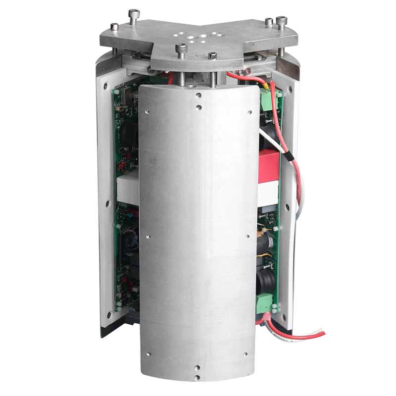
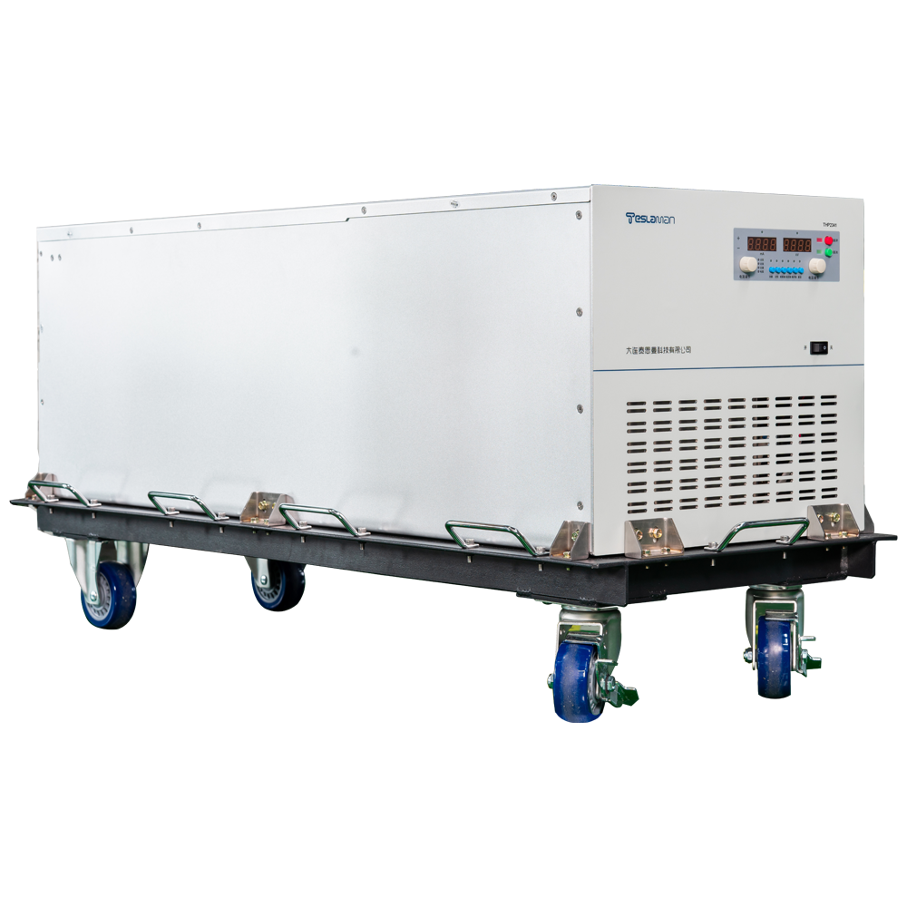
Ion Beam System High-Voltage Power Supply Precision in Semiconductor Doping and Ion Etching Processes
Ion beam systems dope semiconductors and etch structures with a precision that depends directly on the accelerating and extraction voltages. The supply that feeds the ion source determines the energy with which ions strike the target, and the stability of that supply sets the reproducibility of doping depth and etch rate across wafers and batches.
Doping depth is set by the acceleration voltage, and the lateral dose distribution is set by the scan system. A drift of a few tenths of a percent in the accelerating voltage shifts the projected range enough to move the junction depth outside tolerance for advanced devices. The supply therefore holds the voltage with a stability budget measured over the entire implant batch, not just over a short stabilization window.
Extraction voltage controls the beam current drawn from the source. The extraction gap is biased by a separate regulated stage, and the two voltages must track each other as the source plasma density fluctuates. Coordinated control of the extraction and acceleration stages keeps the beam optics stable, which in turn keeps the beam spot size constant during scanning.
Ripple on the acceleration voltage spreads the ion energy distribution. A broadened energy distribution blurs the doping front and reduces etch anisotropy, so the output filter is tuned to hold ripple well below the application tolerance. The filter network is designed with margin for capacitor aging, and the ripple is verified at periodic intervals using a calibrated divider.
Transient response is exercised continuously during scanning. The scan system moves the beam across the wafer, and the target loading seen by the supply varies with the beam position and the wafer pattern. The control loop absorbs these variations, and the measured beam current stays within a narrow band across the full scan field.
Arc events in the source or the beamline trigger a protection sequence. The supply detects the current spike, collapses the output quickly to extinguish the arc, and then ramps back up after a programmed delay. The arc counter feeds the maintenance log, because a rising arc rate usually indicates source degradation rather than a supply fault.
Temperature inside the cabinet shifts the reference and the divider resistors. The supply includes a compensation channel that measures the internal temperature and corrects the setpoint accordingly, which keeps the delivered voltage stable while the cabinet warms up after a cold start. Field records show that compensated units hold specification within twenty minutes of power-on.
Calibration discipline anchors the long-term process. A yearly comparison against a traceable divider verifies both voltage accuracy and ripple at the operating points used by the production recipes. The calibration data is stored with the equipment history, and the drift trend determines when a component-level repair is scheduled rather than relying on a fixed interval.
Documentation control ensures that the drawings, the manuals, and the configuration records reflect the installed equipment. Any modification is documented with the change reason and the verification result. The document set is reviewed at planned intervals, and the obsolete versions are archived rather than discarded.
Spare parts management matches the stock level to the failure statistics of the equipment family. The fast-moving parts are kept on site, and the slow-moving parts are sourced on demand. The stock review is performed quarterly, and the review data include the part cost and the delivery lead time.
Safety procedures around the high-voltage equipment are written, reviewed, and rehearsed. The procedures cover the access control, the discharge sequence, and the use of personal protective equipment. The rehearsal results are recorded, and the procedure is revised when the rehearsal reveals a gap.
Environmental control in the equipment room stabilizes the operating conditions of the supply. The temperature and the humidity are monitored continuously, and the alarm thresholds are set to protect the insulation and the electronics. The environmental records are kept alongside the equipment log for the correlation analysis.
Data analysis turns the logged operating data into maintenance decisions. The voltage, current, temperature, and alarm trends are reviewed at planned intervals, and the deviations from the baseline trigger an investigation. The analysis report is shared with the engineering team and the maintenance crew.
Reliability assessment uses the field data collected from the equipment population. The failure rate, the repair time, and the availability are computed over a rolling period, and the results are compared with the design targets. The assessment output feeds the capital replacement plan and the spares strategy.
Energy efficiency of the supply affects the operating cost and the cooling load. The efficiency is measured at the representative operating points, and the improvement opportunities are evaluated against the implementation cost. The efficiency records are maintained for the lifetime comparison.
Training programs for the operating and maintenance staff are scheduled at defined intervals. The training covers the safe operation, the routine checks, and the fault diagnosis flow. The training effectiveness is verified with a written test and a practical exercise, and the results are filed with the personnel records.
Process qualification is performed whenever the equipment or the process recipe changes. The qualification plan defines the test articles, the acceptance criteria, and the data to be recorded. The qualification report is approved before the new condition enters production.
Failure analysis follows a defined path from the symptom to the root cause. The analysis uses the logged data, the physical evidence, and the repair records. The analysis conclusion is documented with the corrective action, and the corrective action is verified after implementation.
Quality records link the equipment performance to the product quality. The operating parameters and the product measurements are filed together, so that a product deviation can be traced to the equipment condition. The record retention period follows the regulatory and contractual requirements.
Vendor coordination covers the technical support, the spare supply, and the repair service. The service level agreement defines the response time and the repair turnaround. The vendor performance is reviewed periodically, and the review outcome influences the future procurement decisions.
Continuous improvement is driven by the analysis of the failure data and the operating experience. Each improvement proposal is assessed for the benefit, the cost, and the risk before implementation. The implemented improvements are tracked for the realized benefit.
Operator handover between shifts includes the equipment status, the pending issues, and the instructions for the current operation. The handover log is signed by both parties, and the entries are concise and factual. The handover discipline maintains the continuity of the operation.